RM06F9533CT Datasheet: Full Specs & Reliability Data
Did you know that thermal stress accounts for over 40% of early failures in surface-mount thick-film resistors? For engineers selecting the RM06F9533CT, understanding its precise reliability data and electrical characteristics is not just about compliance—it’s about ensuring long-term circuit stability. This guide breaks down the critical RM06F9533CT datasheet parameters, from resistance tolerance to failure rate predictions, providing the hard numbers needed for robust design decisions in high-volume US manufacturing.
Electrical Characteristics Deep Dive

| Parameter | Specification | Unit/Condition |
|---|---|---|
| Nominal Resistance | 953 | kΩ |
| Tolerance | ±1 | % |
| TCR | ±100 | ppm/°C (-55 to +155) |
| Rated Power | 0.1 | W @ 70°C Ambient |
| Package Size | 0603 | Metric (1.6 x 0.8 mm) |
Resistance Value & Tolerance Precision
You must analyze the nominal 953 kΩ value carefully. The ±1% tolerance band defines the strict boundaries within which the component operates. In precision analog circuits, such tight tolerances directly impact signal integrity. A deviation beyond this range can introduce significant errors in voltage dividers or feedback loops. Therefore, verifying the actual measured resistance against these specifications during incoming inspection is a best practice for maintaining circuit accuracy.
Temperature Coefficient (TCR) Impact
The standard RM06F9533CT datasheet documents typically specify a Temperature Coefficient of Resistance (TCR) of ±100 ppm/°C. You should calculate resistance drift across typical operating ranges, specifically from -55°C to +155°C. Over this 210°C span, the potential resistance shift can reach approximately 2.1%. This level of drift is critical in temperature-sensitive applications. Understanding how thermal variations affect the resistor ensures you can predict performance degradation before it impacts system reliability.
Physical Dimensions & Power Ratings
0603 Metric Package Specifications
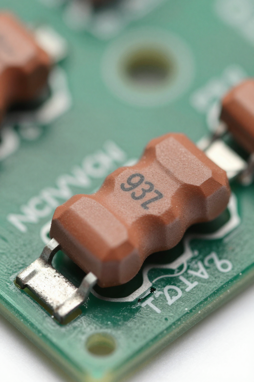
The RM06F9533CT utilizes the 0603 metric package, with footprint dimensions of 1.6mm x 0.8mm. When comparing mechanical stress resistance, this smaller form factor presents different challenges than larger packages like 0805 or 1206. While it saves board space, the reduced solder joint area requires careful handling during assembly. Ensuring proper pad design and stencil aperture ratios helps mitigate risks associated with tombstoning or insufficient wetting, which are more prevalent in compact SMD components.
Power Dissipation Limits
You must clarify the power rating of 0.1W (1/10W) at an ambient temperature of 70°C. Industrial applications often involve higher thermal environments, necessitating derating curves. As ambient temperature rises above 70°C, the maximum allowable power dissipation decreases linearly until it reaches zero at 155°C. Adhering to these derating guidelines prevents overheating and extends the component's lifespan, particularly in densely populated PCBs where heat accumulation is a concern.
Reliability Data & Failure Analysis
Accelerated Life Testing Results
Interpreting key metrics from reliability data is essential for predicting Mean Time Between Failures (MTBF). Accelerated life tests reveal performance under humidity bias and thermal cycling conditions. These tests simulate years of operation in weeks, highlighting potential weak points. By analyzing failure rates under extreme stress, you can assess the robustness of the thick-film construction and ensure it meets industry standards for long-term durability in consumer electronics.
Solder Joint Integrity & Moisture Sensitivity
Review the Moisture Sensitivity Level (MSL) ratings provided in the documentation. Proper reflow profile recommendations are crucial to avoid delamination or cracking during soldering. Thermal expansion mismatch between the resistor body and the PCB substrate can lead to joint fatigue over time. Addressing these potential failure modes through controlled heating rates and peak temperatures ensures strong, reliable solder joints that withstand mechanical and thermal stresses throughout the product lifecycle.
Application-Specific Design Guidelines
Best Use Cases for High-Resistance Values
Identify optimal scenarios for 953 kΩ resistors, such as voltage dividers and pull-up networks in low-current digital logic interfaces. However, be cautious in noise-sensitive applications. High-resistance values can act as antennas for electromagnetic interference (EMI), potentially outweighing their benefits. Evaluating the trade-off between impedance matching and noise immunity is vital for designing stable circuits in mixed-signal environments.
Layout Recommendations for Noise Reduction
Offer practical tips on trace routing and grounding to minimize parasitic capacitance effects. Shorter traces reduce loop areas, decreasing susceptibility to noise pickup. Ensure compatibility with automated pick-and-place processes common in US supply chains by maintaining consistent land patterns. Proper layout techniques enhance the performance of the RM06F9533CT, leveraging its precision while mitigating external interference factors that could compromise signal quality.
Key Takeaways
- The RM06F9533CT offers ±1% tolerance and ±100 ppm/°C TCR, suitable for precision analog designs.
- Power derating is critical; limit dissipation to 0.1W at 70°C ambient to prevent thermal failure.
- Reliability data indicates robust performance under thermal cycling if MSL and reflow guidelines are followed.
- Use 953 kΩ values in voltage dividers but monitor for EMI sensitivity in noisy environments.
Frequently Asked Questions
What is the main advantage of the RM06F9533CT datasheet specs?
The primary advantage lies in its balance of size and precision. The 0603 package allows for dense layouts while maintaining a ±1% tolerance. This combination makes it ideal for space-constrained devices requiring accurate resistance values without the bulk of larger components.
How does temperature affect the RM06F9533CT reliability data?
Temperature significantly influences reliability. With a TCR of ±100 ppm/°C, resistance shifts occur as temperatures change. Additionally, power derating curves show that capacity drops sharply above 70°C. Monitoring thermal management ensures the component stays within safe operating limits defined by its reliability data.
Can I use the RM06F9533CT in high-frequency applications?
While possible, caution is advised. High resistance values can increase parasitic capacitance effects and susceptibility to noise. For high-frequency circuits, verify that the layout minimizes stray capacitance and consider if lower resistance alternatives better suit the impedance requirements of your specific application.
What are the critical failure modes for this resistor?
Thermal stress accounts for over 40% of early failures. Key risks include overheating due to insufficient power derating, tombstoning during assembly due to improper pad design, and delamination from moisture sensitivity violations during reflow.