RM06F8202CT Datasheet Breakdown: Critical Specs for US Engineers
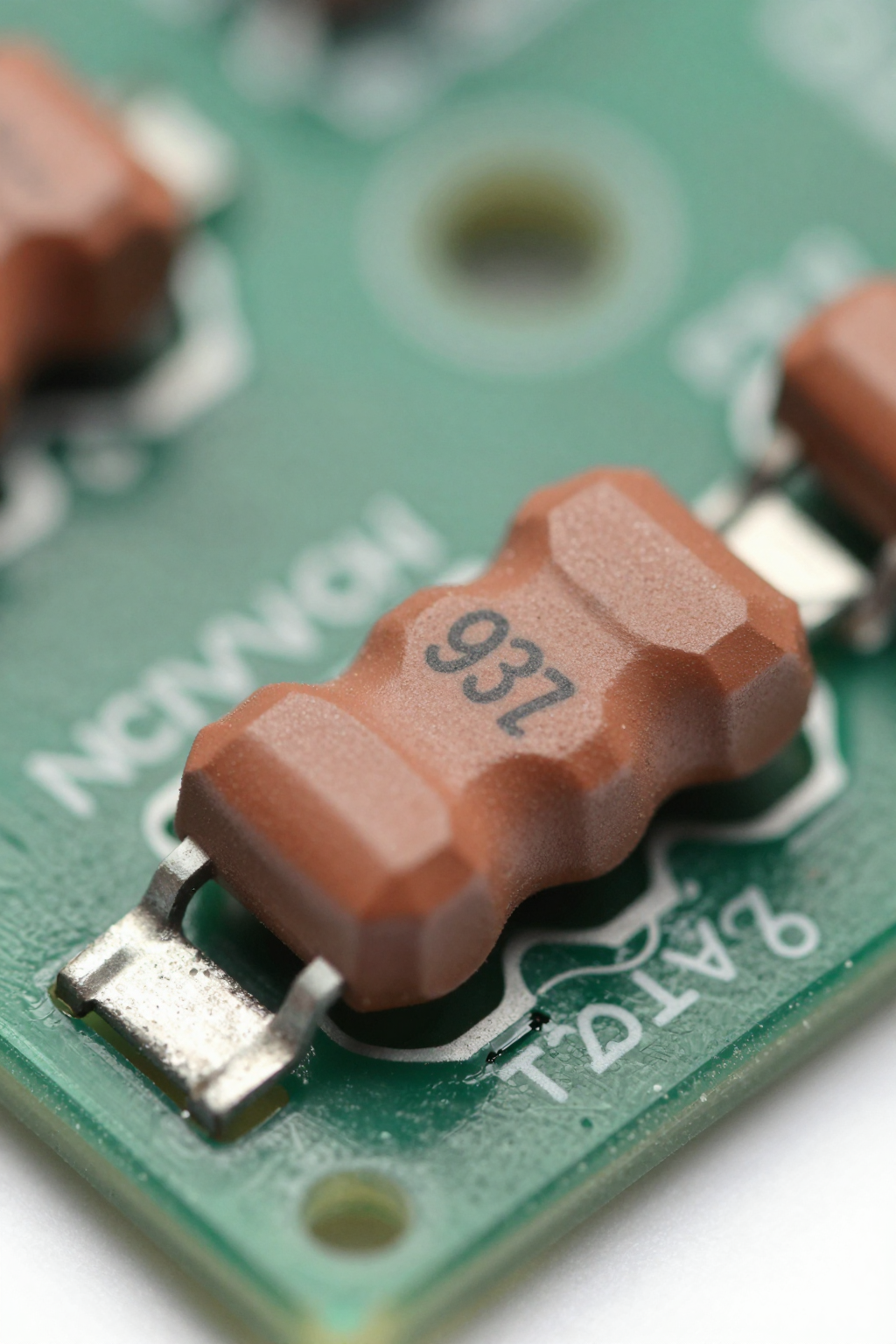
In high-density PCB designs, the 0603 package is no longer just a space-saver—it’s a precision requirement. The RM06F8202CT, a thick-film chip resistor with a nominal resistance of 8.2 kΩ and ±1% tolerance, exemplifies the critical balance between miniaturization and reliability that defines modern US engineering standards. This breakdown dissects the datasheet to reveal why this specific component matters in automotive-grade and industrial control applications.
Decoding the RM06F8202CT Part Number Structure

You need to understand what each character signifies before selecting components for mass production. The part number encodes vital information about physical size, electrical characteristics, and packaging style, ensuring you match the correct specifications to your schematic requirements.
Manufacturer Prefix & Series Identification
The "RM" prefix typically denotes a rectangular, thick-film series designed for general-purpose use but often upgraded for stability. In US manufacturing contexts, identifying the series helps you trace back to specific material compositions. You should verify if the substrate uses alumina or other ceramics, as this affects thermal conductivity. Understanding the series lineage ensures compatibility with existing reflow profiles used in your facility.
Resistance Value & Tolerance Code Analysis
The "8202" code represents the resistance value using standard EIA marking conventions. Here, "820" indicates the significant digits (820 Ω) and "2" represents the multiplier (10²), resulting in 8.2 kΩ. The "C" suffix usually designates a ±1% tolerance. For you, this tight tolerance is crucial in signal conditioning circuits where voltage division accuracy directly impacts sensor data integrity. Misinterpreting these codes can lead to systematic errors in calibration routines.
Electrical Performance Under Load Conditions
Datasheets provide theoretical limits, but real-world application requires understanding how performance degrades under stress. You must analyze power handling and temperature effects to prevent premature failure in enclosed electronic housings.
Rated Power Dissipation at 70°C Ambient
The RM06F8202CT typically features a rated power dissipation of 0.1 W (1/10 W) at an ambient temperature of 70°C. However, derating curves show that above this threshold, allowable power decreases linearly until it reaches zero at approximately 155°C. If you operate in hotter environments, such as near heat sinks or inside automotive dashboards, you must apply strict derating factors. Overlooking this leads to hot spots that accelerate electromigration within the resistive element.
| Ambient Temperature | Max Power Rating | Derating Factor |
|---|---|---|
| ≤ 70°C | 0.10 W | 100% |
| 100°C | ~0.06 W | 60% |
| 155°C | 0 W | 0% |
Temperature Coefficient of Resistance (TCR) Impact
Thick-film resistors like this one generally exhibit a TCR range of ±100 to ±200 ppm/°C. While higher than thin-film alternatives, this specification is acceptable for many control loops. You should calculate the total resistance shift across your operating temperature range. For instance, a 50°C swing could result in a 0.5% to 1% change in resistance. In precision analog front-ends, this drift might necessitate software compensation or additional filtering stages to maintain signal fidelity.
Physical Dimensions & Solder Joint Reliability
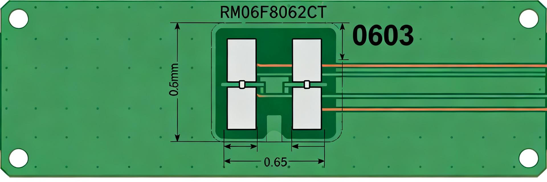
Mechanical stability is as important as electrical specs. The 0603 footprint presents unique challenges for automated assembly lines common in US electronics manufacturing. You must ensure pad layouts align perfectly with manufacturer recommendations to avoid tombstoning or void formation.
Exact Footprint Compatibility for Reflow Profiles
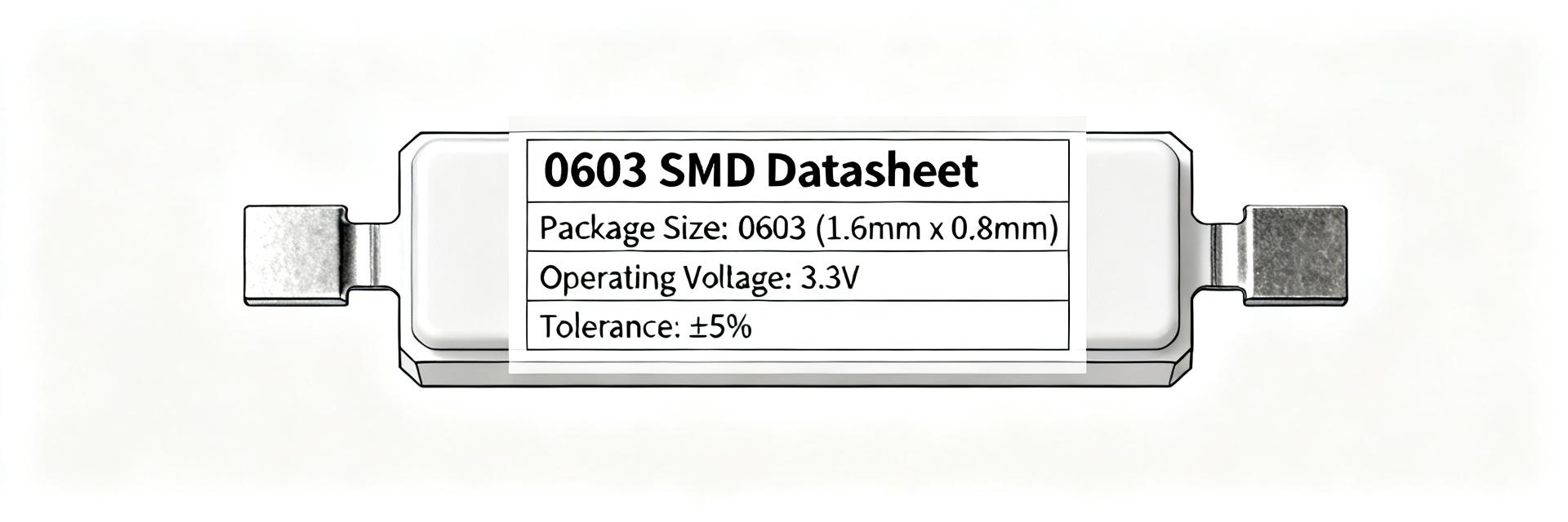
The physical dimensions are strictly defined: length 1.60 mm, width 0.80 mm, and height 0.45 mm. These tolerances require precise stencil printing during surface mount technology (SMT) processes. If you adjust reflow temperatures without accounting for the small thermal mass of the 0603 package, you risk overheating the component. Standard lead-free solder profiles work well, but peak temperatures should not exceed 260°C for more than 10 seconds to preserve the integrity of the resistive layer.
Thermal Shock Resistance in Automotive Environments
Automotive applications demand rigorous testing against thermal cycling. The RM06F8202CT is often qualified for AEC-Q200 standards, meaning it withstands -55°C to +155°C cycles. You should inspect post-reflow joints for micro-cracks, which are invisible to the naked eye but fatal over time. Using X-ray inspection or acoustic microscopy during pilot runs helps identify weak solder joints early. This proactive approach saves costly recalls later in the product lifecycle.
Comparison with Standard E-Series Alternatives
Selecting the right resistor involves balancing cost, availability, and performance. You must evaluate whether the RM06F8202CT offers advantages over generic alternatives in your specific design context.
Precision vs. General-Purpose Thick Film Options
General-purpose thick film resistors may offer wider tolerances (±5%) at lower costs. However, the ±1% precision of the RM06F8202CT reduces variability in mass-produced units. For you, this means less need for trimming potentiometers or complex calibration procedures on the assembly line. The initial component cost difference is negligible compared to labor savings from simplified testing protocols.
Cost-Benefit Analysis for High-Volume Production
In high-volume scenarios, supply chain stability becomes paramount. Common E-series values like 8.2 kΩ are widely stocked, reducing lead times. You should consider total cost of ownership rather than unit price alone. Higher reliability reduces warranty claims and return rates. Additionally, standardized footprints allow you to swap suppliers without redesigning PCB layouts, providing flexibility when market conditions fluctuate.
Key Takeaways
- Part Number Clarity: Understand that "8202" equals 8.2 kΩ and "C" signifies ±1% tolerance, critical for precision circuit design.
- Power Derating: Adhere to the 0.1 W rating at 70°C; apply strict derating curves for higher ambient temperatures to prevent thermal failure.
- TCR Management: Account for ±100–200 ppm/°C drift in temperature-sensitive applications, potentially requiring software compensation.
- SMT Reliability: Ensure exact 0603 footprint compatibility and monitor reflow profiles to avoid tombstoning and micro-cracks.
- Cost Efficiency: Choose this precise resistor over cheaper alternatives to reduce calibration labor and improve long-term reliability.
Frequently Asked Questions
What does the RM06F8202CT tolerance code mean?
The "C" suffix in the part number indicates a ±1% resistance tolerance. This is tighter than standard ±5% options, making it suitable for applications requiring precise voltage division or current sensing. You should select this level of accuracy when signal integrity is critical to system performance.
Can I use RM06F8202CT in automotive applications?
Yes, provided it meets AEC-Q200 qualification standards. Check the specific datasheet revision for temperature range compliance (-55°C to +155°C). You must also ensure proper solder joint design to withstand vibration and thermal shock inherent in vehicle environments.
How do I calculate power dissipation for this resistor?
Use the formula P = V²/R or P = I²R. Ensure the calculated power stays below 0.1 W at 70°C ambient. If your environment is hotter, apply the derating curve specified in the datasheet to determine the maximum allowable power at that specific temperature.
Why is the 0603 footprint challenging for SMT assembly?
The small size requires precise stencil printing and controlled reflow profiles to avoid tombstoning or void formation. Peak temperatures should not exceed 260°C for more than 10 seconds to preserve resistive layer integrity.