353630260 连接器规格报告:引脚、间距及额定值
Distributor and BOM-aggregation datasets indicate that 2.00mm-pitch wire-to-board headers remain among the most specified connector families for compact electronics. Within that cohort, the 353630260 connector is widely specified for 2-pin right-angle board-to-wire interfaces because of its compact form factor and defined pin ratings.
1 — Product overview & quick specs snapshot
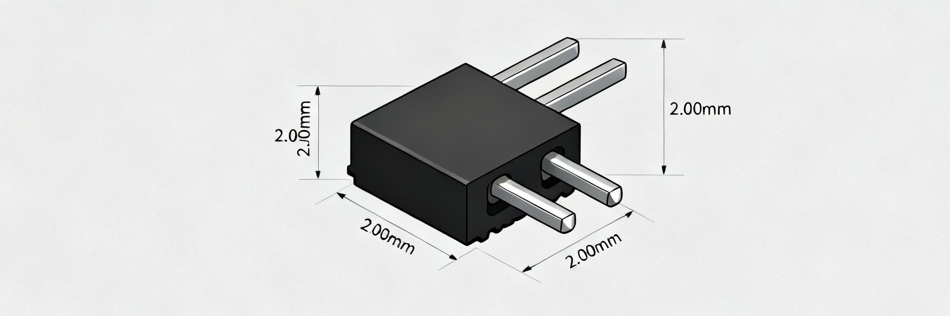
The 353630260 is a 2-pin, right-angle wire-to-board header featuring a 2.00mm pitch and through-hole termination. Its compact spacing is optimized for small battery or signal links where board real estate is at a premium.
| Attribute | Typical Value / Range |
|---|---|
| Part type | 2-pin right-angle wire-to-board header |
| Pitch | 2.00mm pitch |
| Termination | Through-hole |
| Contact plating | Tin or gold options |
| Orientation | Right-angle |
2 — Electrical ratings & pin ratings deep-dive
Per-pin current and voltage ratings derive from contact geometry and plating. Ratings assume specific temperature rise limits; engineers should treat catalog values as absolute maximums.
2.1 Per-pin current & voltage ratings
Design at ≤80% of continuous rating for sustained loads. Verify inrush scenarios separately to prevent contact overheating. Ratings typically fall in the low single-digit ampere range depending on wire gauge and environment.
3 — Mechanical & pitch details: 2.00mm pitch
The 2.00mm pitch imposes layout constraints. Through-hole barrels must fit drill sizes compatible with the pin shank while maintaining adequate annular rings.
3.1 PCB footprint and layout rules
For 2.00mm pitch, use pad centers at exactly 2.00mm. Recommended drill range is 0.9–1.1mm. Maintain an annular ring of ≥0.15mm and a 0.5–1.0mm keepout for side-entry housings.
4 — Testing, reliability & compliance
Pre-production testing is vital. Standard sequences include continuity, thermal-current soak, mating cycles, and vibration/shock resistance per IPC standards.
5 — Application examples & failure modes
Commonly found in battery connections, sensor leads, and tamper switches. Typical failures include cold solder joints or bent pins; these are mitigated by proper solder profiling and mechanical reinforcement.
6 — Implementation checklist
- Verify exact pin count/pitch vs footprint.
- Request RoHS and UL 94 V-0 flammability data.
- Perform solderability and mating cycle tests on samples.
Summary
The 353630260 header requires careful attention to derating and PCB layout. Validating thermal performance and mechanical retention ensures long-term reliability in compact 2-pin interface designs.
What is the best way to verify pin ratings for a 353630260 connector?
Perform a current-carrying thermal soak on samples at the intended continuous current and measure temperature rise at the contact and solder fillet. Compare measured rise to the supplier’s allowable temperature limit and apply a design derating (typically ≤80% continuous).
How should a PCB footprint be adjusted for 2.00mm pitch headers?
Use exact 2.00mm pad centers, choose a drill size matching the pin shank (commonly 0.9–1.1mm), ensure annular ring ≥0.15mm and keep silkscreen clear of pads. Allow a 0.5–1.0mm courtyard for side-entry housings.
Which tests are critical to run before volume buying a 2-pin 2.00mm header?
Critical tests include: solderability, contact resistance after environmental stress, thermal current soak, mating/unmating cycles and vibration. Use at least 5–10 samples for initial qualification.
When should engineers choose the 353630260 right-angle header?
This part is ideal when board space is constrained and a polarized mating interface is required for battery, sensor, or signal connections where a right-angle cable exit is necessary for the enclosure design.