
35507-0200 connector: Spec Breakdown & Key Datasheet
The 35507-0200 connector is a compact 2-position, 2.00 mm pitch wire-to-board female housing commonly used for low-current signal and small-power links. Typical ratings are ~2 A per contact and ~125 V, with defined contact and insulation resistances and operating temperature limits that determine suitability for portable and instrumentation designs.
Background & Application
Design basics & form factor
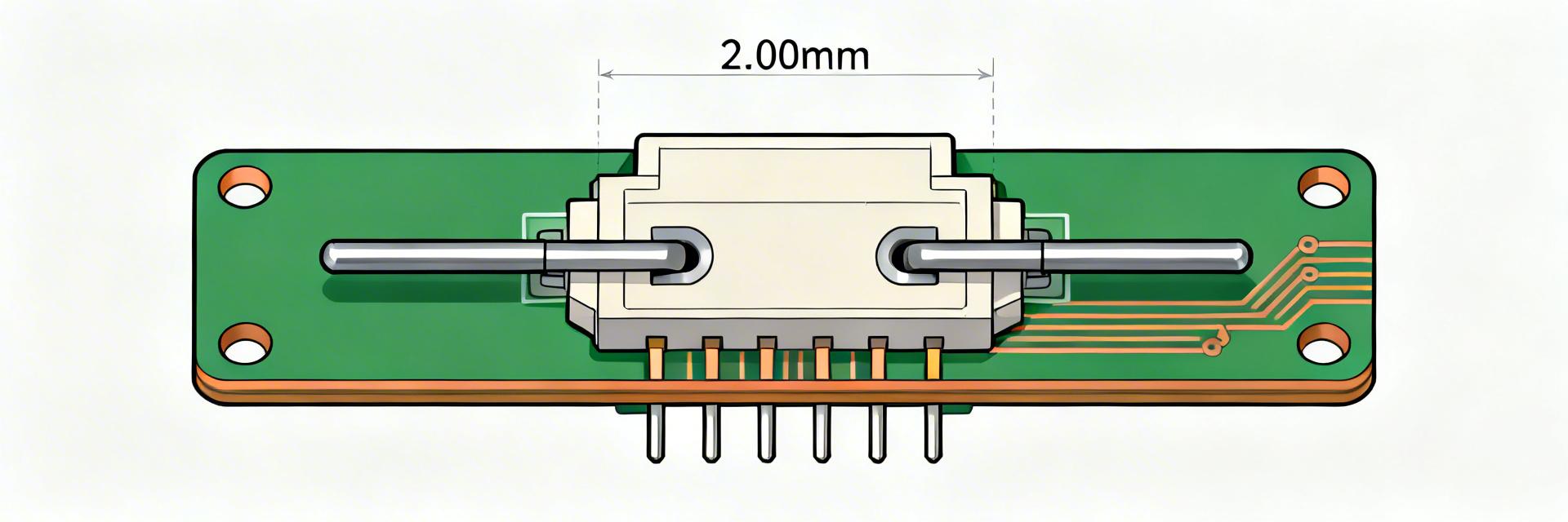
The housing is a 2-position, single-row, 2.00 mm pitch wire-to-board female type intended for straight cable entry; right-angle variants exist in the same family. Termination is normally crimp-to-wire contacts inserted into a plastic insulator; mating is cable-to-board. Compared with 1.25 mm micro-pitch or legacy 2.54 mm, 2.00 mm balances density and robust contact area.
Typical application spaces
Use-cases include battery leads in portable electronics, sensor and module connections, small instrumentation, and control boards where space and low current suffice. These locations often demand compact footprints, low-mass cables, and moderate vibration tolerance, making the design common in constrained enclosures and light-duty internal harnesses.
Mechanical Specifications
Key Dimensions for CAD
Pitch (2.00 mm), overall housing length/width/height, pin centerline to board edge, mating depth, and latch/polarization features. Also capture recommended PCB footprint, pad size, solder mask keepouts, and mechanical tolerance notes.
Materials & Durability
Typical insulator material is a high-temperature thermoplastic; contacts are copper alloy with tin or optional gold plating. Datasheets list insertion/removal cycles (mechanical life). Choice of plating affects solderability, corrosion resistance and wear: tin is common and economical, gold improves low-voltage reliability and mating endurance.
Electrical & Environmental Performance
| Parameter | Standard Rating | Key Considerations |
|---|---|---|
| Rated Current | ~2 A per contact | Dependent on wire gauge and total circuits |
| Max Voltage | ~125 V | AC (RMS) or DC equivalent |
| Temperature Range | -40°C to +105°C | Includes ambient + temperature rise from current |
Electrical ratings & test conditions
Initial contact resistance (milliohms), insulation resistance (megaohms), and dielectric withstanding voltage. Always note the exact test conditions shown in the specs table, including temperature and measurement methodology.
Environmental ratings
Extract operating and storage temperature ranges. If available, capture any IP or sealing statements. Current and voltage capability often drops at temperature extremes—use published derating curves.
How to read the datasheet
Sections to scan first
Prioritize part overview, absolute maximum ratings, electrical characteristics, mechanical drawings, and ordering information. Create a checklist: current rating, contact resistance, mating force, and plating finish options.
Common datasheet gotchas
Watch footnotes that alter test conditions (e.g., values “without contacts”). Clarify whether current ratings are per-contact or dependent on total housing temperature rise; confirm cable gauge and crimp data.
Design & Mounting
PCB layout & orientation
Keep solder pads within recommended dimensions and respect solder-mask clearance. Orient the connector so cable routing minimizes bends at the latch; place strain relief features nearby. Allow clearance for keyed insertion.
Mechanical retention
Design for latch engagement and add a defined tie point. Common failure modes include bent contacts from improper insertion and crimped contact deformation—inspect samples after first-run assembly.
Procurement & Final Checklist
Pre-Order Confirmation
- Confirm exact part number and variant.
- Check if contacts are included or shipped separately.
- Verify plating finish and RoHS compliance.
- Assess MOQ and lead time for production.
- Order 5–10 extra samples for destructive testing.
Prototype Validation
- Continuity and low-resistance measurement.
- Mechanical mating cycles to rated life.
- Thermal cycling for junction stability.
- Vibration testing for mobile environments.
- Verify resistance drift stays within datasheet limits.
Summary
- ● The 35507-0200 connector is a 2-pos, 2.00 mm pitch wire-to-board housing—capture pitch, mating depth, and PCB footprint before layout decisions.
- ● Record electrical and environmental specs from the datasheet table, paying attention to test conditions and derating guidance to validate current/voltage capability.
- ● Follow practical layout, strain-relief and procurement checks, and run prototype tests (continuity, thermal, cycles) to verify long-term reliability before production.





