
RM06J131CT Full Datasheet: 0603 SMD Specs & Tests Explained
RM06J131CT Full Datasheet: 0603 SMD Specs & Tests Explained
Point: A concise, data-driven read of common 0603 SMD resistor datasheets speeds design, testing, and buying decisions. Evidence: Typical datasheets list resistance, tolerance, power rating, temp coefficient, package drawing, and test results; these fields determine real-world fit. Explanation: Focusing on those fields reduces rework, ensures footprint compatibility, and shortens procurement cycles for parts like RM06J131CT.
Point: Knowing how to parse a datasheet prevents costly mistakes in assembly and reliability validation. Evidence: The RM06J131CT identifier, electrical specs, and test tables are the immediate checkpoints engineers use. Explanation: This guide walks through those sections so designers can extract the critical parameters from the datasheet and apply them to schematic, PCB, and test plans.
1 — Part overview & what the RM06J131CT label means
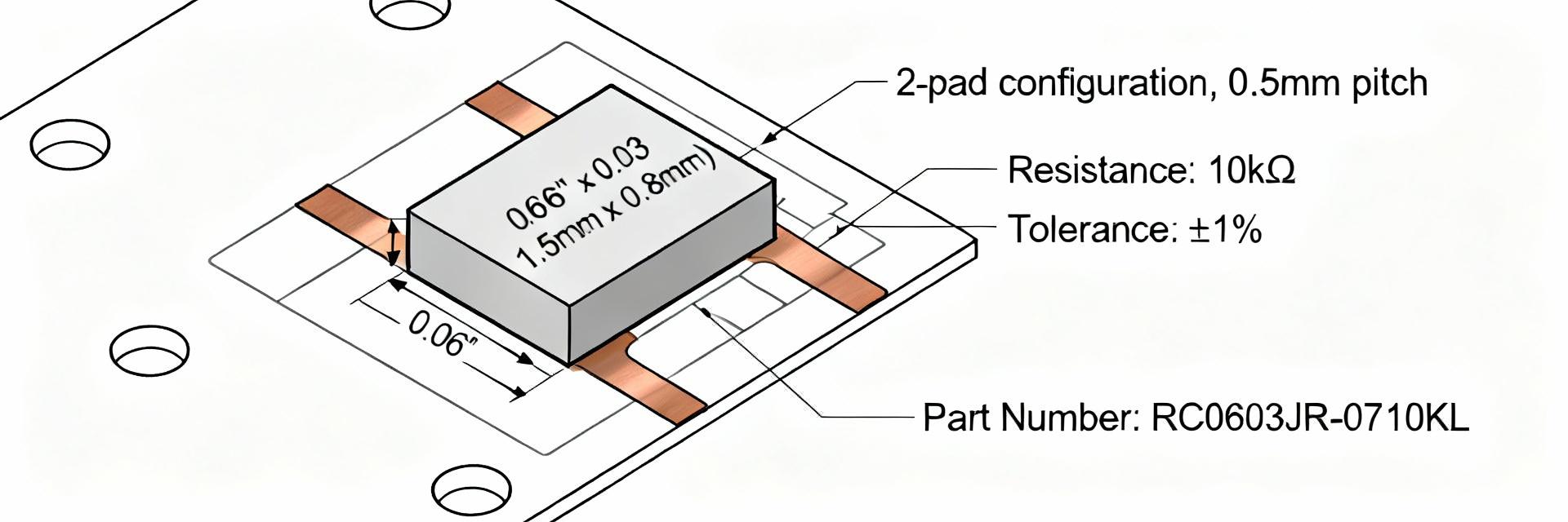
1.1 — Identifier breakdown
Point: Part markings encode series, size, resistance, tolerance, and packaging suffix. Evidence: In codes like RM06J131CT, "RM" commonly flags series, "06" denotes 0603 size, "131" decodes to 130Ω, and trailing letters indicate tolerance or tape-and-reel packaging. Explanation: Use this parsing rule to map similar part numbers back to the datasheet fields that confirm electrical and mechanical attributes before ordering.
1.2 — Typical use cases for a 0603 SMD resistor
Point: 0603 SMD resistors are chosen for space-constrained, high-volume assemblies. Evidence: Their common roles include pull-up/pull-down functions, current sense in low-side networks, and passive filtering in compact analog or digital nets. Explanation: Designers select 0603 SMD for automated pick-and-place compatibility, acceptable power dissipation in low-power circuits, and minimal board area impact.
2 — Quick specs reference (how to read the datasheet at a glance)
2.1 — Key electrical specs to extract first
Point: Capture resistance value, tolerance, power rating, tempco, and operating range first. Evidence: For 0603 parts expect ~0.1 W power rating, tempco commonly ±100 ppm/°C for thick-film, and tolerances like ±1% or ±5%. Explanation: Recording these in a short template (value / tol / power / tempco / op temp) lets you compare candidates quickly when the datasheet includes tables and charts.
2.2 — Package and mechanical specs
Point: Verify footprint dimensions and land pattern recommendations from the mechanical drawing. Evidence: 0603 nominal dimensions are roughly 0.063" × 0.031" (1.60 × 0.80 mm) with seated height ~0.020" (0.5 mm); datasheets list tolerances and recommended pad geometries. Explanation: Confirm length, width, height, and land tolerance in the datasheet against your PCB CAD library to avoid solderability issues.
3 — Electrical & environmental test results explained
3.1 — Common electrical tests and what the numbers mean
Point: Read DC resistance tolerance, power derating curve, surge withstand, and tempco carefully. Evidence: Datasheet graphs show how allowable dissipation declines with temperature and list surge or overload test limits and resistance change after stress. Explanation: Use pass/fail thresholds from the datasheet to set incoming inspection limits and guardrails for circuit derating under worst-case conditions.
3.2 — Environmental, life, and reliability tests
Point: Compare thermal shock, IR reflow compliance, humidity, and high-temperature storage results to your end-use profile. Evidence: Typical 0603 SMD test matrices include thermal shock cycles, IR reflow at JEDEC-compatible profiles, and humidity soak with resistance drift metrics. Explanation: Match the datasheet test conditions to expected field conditions—if ambient or cycling is harsher, upgrade the spec or add qualification testing.
4 — Assembly, soldering and reliability best practices for 0603 SMD
4.1 — Recommended PCB footprint & solder paste stencil guidance
Point: Follow the datasheet land pattern and IPC recommendations for reliable joints. Evidence: Datasheets provide pad geometry and suggest stencil aperture percent; common practice uses 60–70% paste coverage of the pad to prevent excess solder and tombstoning. Explanation: Use the datasheet’s footprint tolerances to finalize stencil apertures and pad fillets, and specify aperture % in your stencil drawing for consistent solder fillets.
4.2 — Reflow profile and handling precautions
Point: Respect the reflow peak temperature and cycle count specified by the datasheet to avoid cracking. Evidence: 0603 SMD parts typically tolerate lead-free peak temperatures up to ~260°C for limited cycles; mechanical handling limits and bending specs are also provided. Explanation: Set oven profiles to the datasheet curve, limit thermal cycles per board, and include handling notes to reduce tombstoning, edge chipping, and substrate-induced stress.
5 — Measurement & troubleshooting: test procedures you can run
5.1 — How to measure resistance accurately on 0603 parts
Point: Use the right instrument technique to get meaningful resistance readings. Evidence: For values above a few ohms a quality 2‑wire DMM is adequate, while lower-ohm or precision checks use 4‑wire Kelvin measurements, controlled test current, and thermal stabilization. Explanation: Include test current, lead compensation, and settling time in your procedure and compare measured variance to the datasheet tolerance and test condition notes.
5.2 — Common failure modes and root-cause checks
Point: Failure signatures map to specific root causes that can be triaged quickly. Evidence: Opens and intermittent opens often indicate solder or mechanical cracks; drift implies thermal or moisture stress; shorts indicate solder bridging or delamination. Explanation: Triage by visual inspection, IR reflow log review, and comparison to solder profile and datasheet stress test limits to isolate process vs. component issues.
6 — Selection, procurement and application checklist
6.1 — Choosing the right variant and verifying specs from the datasheet
Point: Follow a short verification checklist before purchase or qualification. Evidence: Confirm resistance & tolerance, power rating, tempco, operating temperature range, package/height, and reflow limits against the datasheet tables and mechanical drawing. Explanation: Require a datasheet review sign-off on these items in procurement to reduce wrong-part purchases and ensure first-pass assembly success for RM06J131CT.
6.2 — Example application scenarios & quick comparison notes
Point: Prioritize different specs depending on the application environment. Evidence: In low-noise analog prioritize low tempco and tight tolerance; in high-temperature automotive prioritize higher temp rating, derating curve, and robust humidity testing. Explanation: Map the datasheet graphs to these priorities—select the variant whose test outcomes and tempco align with the dominant design constraint.
Key summary
- Check the core datasheet fields first: resistance, tolerance, power rating, tempco, and operating range to rapidly qualify 0603 SMD candidates for PCB and circuit fit.
- Verify mechanical drawing: confirm 0603 nominal dimensions (≈0.063"×0.031") and land pattern tolerances in the datasheet before committing a footprint.
- Use datasheet test limits—derating curves, reflow temp, and humidity results—to set inspection criteria and process controls for reliable assembly.
Frequently Asked Questions
How should I confirm the RM06J131CT resistance code from the datasheet?
Point: Translate the part code to resistance using standard coding rules. Evidence: Numeric segments like "131" traditionally indicate 13 × 10^1 = 130Ω; the datasheet table confirms the nominal ohmic value and tolerance under specified test conditions. Explanation: Cross-check the code against the datasheet’s resistance table and verify tolerance and measurement conditions before accepting samples.
What reflow profile should I use for 0603 SMD parts according to typical datasheets?
Point: Apply a JEDEC-compatible peak and ramp profile within datasheet limits. Evidence: Typical lead-free guidance shows a peak near 260°C with controlled ramp and specified time above liquidus and limited cycle counts. Explanation: Program oven profiles to the datasheet curve, limit machine variability, and log each board’s cycles to maintain component reliability.
When measuring small drift on a 0603 resistor, how do I determine if it failed the datasheet spec?
Point: Compare measured drift against datasheet test-condition delta and tolerance. Evidence: Datasheets report resistance change after stress tests and define pass thresholds; measurement must replicate the same test conditions or be adjusted for test-current and ambient differences. Explanation: Reproduce the datasheet test conditions where possible, use proper instrumentation, and only classify drift as failure when it exceeds the datasheet-specified post-test limits.
Summary
Point: A focused datasheet read cuts risk in design, assembly, and procurement. Evidence: For RM06J131CT, confirming resistance, tolerance, power rating, tempco, mechanical drawing, and test matrices yields actionable acceptance criteria. Explanation: Use the outlined checklists, measurement steps, and assembly guidance to ensure the selected 0603 SMD part meets circuit needs and reliability expectations; follow the word-count split guidance for documentation.





