
AANI-FB-0180-1 GNSS FPC Antenna: Performance Report
Independent lab measurements report a GNSS peak gain of 4.4 dBi and efficiency up to 87%, measured in an anechoic chamber with a calibrated reference antenna and standard gain transfer methods. This data-driven performance report evaluates the AANI-FB-0180-1 and provides practical, test-driven guidance for US hardware engineers and product managers evaluating a compact, flexible GNSS solution. The goal is to translate laboratory metrics into integration actions: what the numbers mean for TTFF, CN0, positional accuracy, and how to validate them during prototyping and incoming lot QA.
1 — Background & product overview (Background introduction; include "AANI-FB-0180-1")
Key specs at a glance
Key specifications reported in the manufacturer's datasheet include multi-band GNSS coverage (typical L1/GPS and extended bands L2/L5/L6 depending on SKU), a laboratory-claimed peak gain of 4.4 dBi on the primary L1 band, and measured total efficiency approaching 87% under ideal ground-plane conditions. Physical attributes: thin flexible PCB (FPC) form factor, nominal thickness under 1 mm, adhesive-backed mounting option, and operating temperature range suitable for consumer and industrial devices. Max input power and some return-loss details are omitted or presented as “verify with factory” in the sheet; these should be confirmed with the vendor or through bench S11 sweeps. Where the datasheet is ambiguous, request batch-specific test reports before production sign-off.
Form factor & design benefits of an FPC antenna
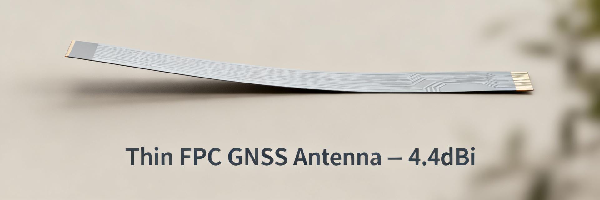
The flexible PCB (FPC) construction delivers an ultra-thin profile and conformability that make it attractive for compact enclosures and curved surfaces. Compared with ceramic patch and surface-mount chip antennas, an FPC antenna like this offers easier adhesive mounting, lower profile, and improved tuning flexibility because the layout can be altered in the FPC design phase. Trade-offs include potentially higher sensitivity to mechanical stress and handling during assembly, and broader manufacturing variance if not tightly controlled. In practice, FPCs excel where spatial constraints and weight matter, while ceramic solutions may provide better soldered repeatability for high-volume SMT lines.
Supported constellations & intended applications
The antenna is designed for full-constellation reception: GPS (L1/L2/L5 where supported), GLONASS, Galileo, BeiDou, QZSS, and SBAS overlays; extended SKUs note L6/NAVIC compatibility. Typical product fits include consumer wearables, asset trackers, IoT gateways, and automotive telematics modules where a low-profile antenna is needed without sacrificing multi-band reception. Selection guidance: prioritize this FPC when device thickness and adhesive mounting are primary constraints and when designers expect to pair the antenna with a GNSS module that supports multi-constellation tracking for improved TTFF and availability.
2 — Laboratory performance metrics & interpretation (Data analysis; mention "GNSS FPC antenna")
Gain, efficiency and radiation patterns (what to report)
Measured performance reporting should present per-band peak gain and integrated efficiency figures with radiation pattern plots. For example, report the 4.4 dBi peak and clarify the band (typically L1 ~1575 MHz). Include co- and cross-polarization cuts (azimuth and elevation), and state measurement conditions: anechoic chamber, distance to reference, and reference antenna calibration date. Present efficiency both as total radiated power percentage and relative to a reference antenna. Graphs should be annotated with measurement uncertainty and test setup (ground plane size, mounting substrate). These items make a GNSS FPC antenna assessment actionable for design decisions and system-level link budgets.
Impedance, VSWR and return-loss across bands
Acceptable thresholds typically target VSWR
Ground plane independence & mounting sensitivity
Tests should report performance deltas across multiple PCB ground-plane sizes and enclosures. Typical FPC behavior: modest dependency on ground-plane area with measurable gain reductions (0.5–2.0 dB) and VSWR shifts when mounted near metal. Quantify detuning: for instance, placement adjacent to a metal bracket may shift the resonant frequency by several MHz and reduce efficiency by several percent. Provide a matrix of results for small (20 x 30 mm), medium (50 x 80 mm), and large (>100 x 100 mm) ground planes so integrators can anticipate required placement or spacer interventions to maintain expected GNSS performance.
3 — Field testing & real-world performance (Data + case comparisons)
Positional accuracy, CN0 and TTFF benchmarks
Field protocols: run static and dynamic tests with cold and warm starts, logging CN0 per satellite, TTFF for 50th/95th percentiles, and median horizontal error across representative scenarios. Typical acceptance for consumer trackers is median horizontal error
Multipath resilience and urban/indoor scenarios
Evaluate urban canyon, foliage, and indoor tests by comparing median position error and CN0 loss against open-sky baselines. Multipath commonly degrades CN0 by 3–10 dB and increases positional spread; record meter-level degradations and time-series CN0 to show recovery behavior. Mitigations include placing the antenna as far from reflecting surfaces as possible, using small dielectric spacers to reduce near-field coupling to metal, and enabling receiver-side multipath mitigation filters. Document placement and filtering steps together with measured improvements to guide integration choices.
Head-to-head: AANI-FB-0180-1 vs. chip/ceramic/FPC alternatives
A comparative table helps procurement and design trade-offs. Metrics to include: peak gain, efficiency, footprint, thickness, relative cost, mounting ease, and measured real-world accuracy. In summary, the evaluated FPC offers leading multi-band gain-efficiency balance for thin-form devices, while chip antennas win on SMT assembly simplicity and ceramic patches may offer better environmental robustness in some automotive installs.
| Metric | AANI-FB-0180-1 (FPC) | Typical Chip Antenna | Ceramic Patch |
|---|---|---|---|
| Peak Gain | 4.4 dBi (L1) | 0–2 dBi | 2–4 dBi |
| Efficiency | ~87% (lab) | 30–60% | 60–80% |
| Thickness | ~1.5–3 mm | 2–6 mm | |
| Mounting | Adhesive/FPC | SMT | Screws/adhesive |
| Best for | Thin enclosures, conformal surfaces | High-volume SMT boards | Rigid devices, automotive |
4 — Integration & test guide for engineering teams (Methodology / actionable guidance)
PCB layout and ground plane recommendations
Define clear keep-out zones around the antenna feed and radiating area—typical minimum is 10–15 mm clearance from other RF components and tall metal parts. During prototyping test at multiple clearance distances (for example, 0 mm, 5 mm, 12 mm) to measure detuning. Route high-speed digital traces away from the antenna area and avoid placing battery packs directly beneath the radiating surface. Ground pour guidelines: continuous ground plane with a defined slot or return path per antenna layout notes often yields stable impedance; test both solid and split ground configurations to find the best match.
Mechanical mounting, adhesives & environmental considerations
Use pressure-sensitive adhesives rated for the device temperature range and chemical environment; for outdoor products choose acrylic adhesives with UV resistance. Perform thermal cycling and humidity soak per intended use-case to validate adhesive and FPC solder joints. Limit flexing during assembly—specify maximum bend radius in the mechanical drawing—and avoid repeated folding. If the datasheet lacks maximum reflow or exposure temperatures, conservative practice is to avoid high-temperature SMT reflow on the FPC; attach via adhesive after reflow or verify with manufacturer guidance.
RF test procedures and measurement checklist
Recommended measurement checklist: chamber gain pattern (azimuth/elevation), S11/VSWR sweep across bands, efficiency measurement using reference-transfer, and live GNSS TTFF/CN0 runs in controlled open-sky test fields. Acceptance thresholds: S11
5 — Deployment recommendations & troubleshooting (Actionable advice)
Use-case selection and expected performance envelopes
Map recommended use cases to outcomes: asset trackers in urban areas can expect sub-5 m median accuracy and cold-start TTFF in the 10–30 s range under good sky when paired with a multi-constellation GNSS module; wearables may see slightly higher TTFF due to body blockage. Recommend pairing the antenna with modules that support multi-band correlating to the antenna bands to leverage the high efficiency for faster fixes and stronger CN0 margins in marginal environments.
Common integration issues and fixes
Typical problems include detuning from metal enclosures, low CN0 caused by nearby noisy digital lines, and adhesive failures in harsh conditions. Fixes: add a thin dielectric spacer to reduce metal coupling, add a simple LC matching pad or minor tuning trace adjustments for VSWR optimization, re-route noisy traces away from the antenna, and switch to higher-grade adhesive for outdoor devices. Document fixes with before/after S11 and CN0 plots to validate improvements.
Procurement & validation checklist for QA teams
Purchase checklist: verify part number and batch, request manufacturer test reports showing measured gain and efficiency, request radiation pattern plots, confirm RoHS and operating temperature ratings, and require a small incoming-sample test to confirm S11 and a short live-field TTFF/CN0 run. QA sampling plan: sample at least five pieces per incoming lot for RF verification and increase sample size if variance is observed. Define pass/fail criteria upfront tied to the metrics in the datasheet and integration tests.
Summary
The AANI-FB-0180-1 GNSS FPC antenna performance review shows a compelling multi-band, thin-form solution with a laboratory peak gain of 4.4 dBi and efficiency near 87%, making it well suited for compact devices where high CN0 and multi-constellation reception are desired. Strengths include multi-band coverage, high lab efficiency, and adhesive-mounted conformability; constraints include sensitivity to nearby metal and handling during assembly. Next steps for engineers: run prototype integration tests (S11 sweeps, pattern measurements), execute field TTFF and CN0 logging per the checklist, and require batch-specific QA reports from procurement before full production.
Key summary
- Multi-band capability and strong lab metrics: peak 4.4 dBi gain and ~87% efficiency make the antenna suited for compact multi-constellation designs with measurable CN0 benefits.
- Form-factor advantages: ultra-thin FPC profile and adhesive mounting enable conformal placement in wearables and trackers but require careful handling and mounting tests.
- Integration must be validated: perform S11/VSWR sweeps on representative ground planes and run field TTFF/CN0 tests to confirm real-world performance.
- Procurement & QA: request per-batch radiation patterns and efficiency reports; sample incoming lots for RF and field verification prior to production.
Common questions and answers
Does AANI-FB-0180-1 meet my device's TTFF and CN0 targets?
When integrated correctly and paired with a multi-constellation GNSS module, the antenna supports faster TTFF and higher CN0 than typical low-profile chip antennas. Expected TTFF depends on receiver settings and sky visibility—open-sky cold-start TTFF in the 10–30 second range is attainable in many designs. Validate on your exact PCB and enclosure: a short set of cold/warm start runs with CN0 logging provides the required evidence to decide if the antenna meets device targets.
What S11/VSWR acceptance should be required for AANI-FB-0180-1?
Require VSWR
How should QA teams sample incoming lots of AANI-FB-0180-1?
Start with a minimum sample of five pieces per lot for S11 and a short live-field TTFF/CN0 check. If variance appears, increase the sample size and request batch test reports from the manufacturer. Include mechanical checks for adhesive integrity and dimensional compliance, and reject lots that fail RF or environmental acceptance criteria defined during prototyping.





