
42815-0114 Specs Report: Electrical Ratings & Limits
Across manufacturer datasheets and distributor technical files, 42815-0114 shows a consistent operating envelope—key temperature, current, and plating metrics that determine its suitability for high-current wire-to-board and wire-to-wire power connections.
This report summarizes electrical ratings, operational limits, test conditions, and practical derating guidance. Our goal is concise, data-driven guidance for design and validation teams.
Product Overview & Key Specs
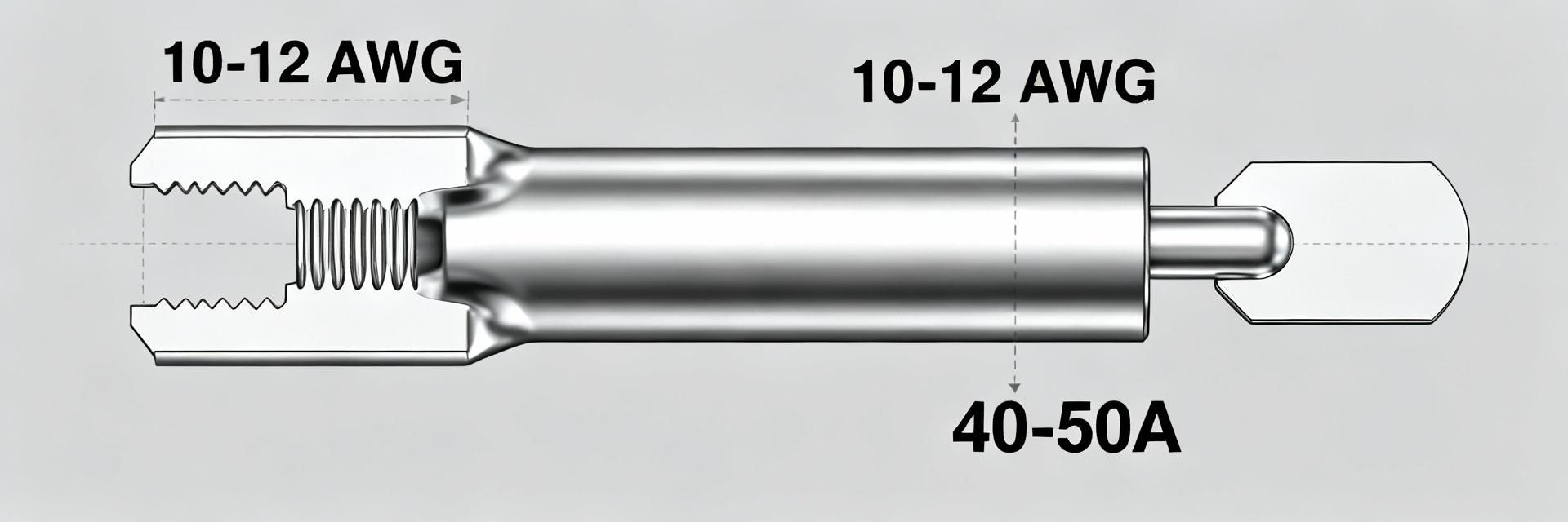
Crimp Socket Context & Typical Applications
The 42815-0114 is a crimp-style socket contact intended for power interconnects in mid-to-high current harnesses. Engineers utilize this contact in wire-to-board and wire-to-wire power paths for:
- • Industrial control equipment and power supplies.
- • Consumer products requiring robust current delivery.
- • Heavy-duty cable assemblies and power distribution units.
Snapshot Spec Table
| Parameter | Typical Value | Visual Indicator |
|---|---|---|
| Wire Gauge Range | 10–12 AWG |
|
| Operating Temperature | -40°C to +105°C |
|
| Typical Current Rating | 40–50 A |
|
| Plating Thickness | ~2.54 μm (Silver/Nickel) |
|
| Mating Cycles | ~30 Cycles |
|
Electrical Ratings: Current, Voltage & Performance
Continuous & Peak Current
Specified under defined conditions like ΔT ≤ 30°C rise. For 12 AWG, safe continuous currents range from 30–40 A, while 10 AWG typically handles 40–50 A. Always apply derating for elevated ambient temperatures.
Voltage & Dielectric Limits
Ratings are verified by dielectric withstand tests (AC for one minute). If an explicit rating is absent, designers must adhere to system-level insulation, creepage, and clearance standards based on the working voltage.
Environmental & Mechanical Limits
Stress & Reliability
Current capacity reduces as temperature rises. A common rule is to apply a 0.8× factor at +40°C ambient. Crimp quality and retention force are vital to preventing intermittent contact under vibration.
Plating & Corrosion
Silver-over-nickel plating (~2.54 μm) lowers resistance but can tarnish. For harsh environments, consider additional sealing or lubrication to protect the base metal conductivity.
How to Validate & Use the Datasheet
"Test conditions to confirm: ambient temp for current rating, sample conductor gauge, measurement interval for resistance, and whether values are typical or guaranteed."
Practical Bench-Level Validation
Recommended setups for real-world performance confirmation:
Selection, Derating & Application Checklist
Quick Calculation Examples
Example 1: 10 AWG Derating
50A (Nominal) × 0.9 (at 40°C) = 45A Recommended
Example 2: Power Dissipation
P = I²R → (40A)² × 0.5mΩ = 0.8W per contact
Executive Summary
- ✓ The 42815-0114 is a power socket for 10–12 AWG with 40–50 A capability when properly cooled.
- ✓ Derate for ambient temperature and bundling; maintain a conservative 10–20% safety margin.
- ✓ Always validate manufacturer claims via bench-level resistance and retention tests before production.





