
16-02-0087 crimp terminal datasheet: full specs & ratings
The 16-02-0087 crimp terminal is a female socket designed for signal and low-power harnesses. The manufacturer datasheet specifies compatibility with 22–24 AWG stranded wire, a typical current rating of 3 A, and a maximum voltage rating up to 600 V.
This breakdown references the official datasheet and drawing as the authoritative source for test conditions and lot-specific limits. Each section follows a point-evidence-explanation structure for quick interpretation and practical design application.
Product Overview: Crimp Terminal
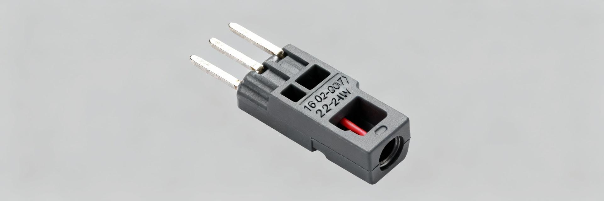
What this terminal is (Purpose & Series Context)
Point: This contact is a female crimp socket intended for low-power wire-to-wire and wire-to-housing connector systems.
Evidence: Datasheet classifies it as a cable-mount, free-hanging crimp contact supplied on reel or in cut-strip format for automated insertion.
Explanation: Use cases include signal harnesses where compact pitch and reliable mating are required. It installs into a mating housing to form wire-to-wire or wire-to-board assemblies and is optimized for stranded conductors in the 22–24 AWG range.
Common Applications and Typical Systems
Point: The terminal is suited to consumer electronics, small appliances, cable assemblies, and control systems.
Evidence: Datasheet and product notes list examples where compact footprint and optional selective plating are desirable.
Explanation: Engineers choose this part for constrained spaces, selective gold/tin plating options for improved contact life, and when verifying mating housing compatibility, current and voltage demands are the primary selection criteria.
Datasheet Electrical Specs
Rated Electrical Values (Current, Voltage, Insulation)
Point: Key electrical ratings define safe operating envelopes. Evidence: The published datasheet lists maximum current ~3 A, maximum voltage 600 V, target contact resistance in the low milliohm range and high insulation resistance.
| Specification | Value | Test Condition / Note |
|---|---|---|
| Maximum current | 3 A (typical) | Continuous rating depends on wire and ambient; verify thermal rise |
| Maximum voltage | 600 V | Dielectric clearance/creepage to be checked in assembled connector |
| Contact resistance | Low milliohm target | Measured after specified mating cycles per datasheet |
| Insulation resistance | High (per datasheet) | Typical >10^9 Ω under standard conditions |
Environmental & Temperature Ratings
Point: Operating temperature range and environmental tests define suitability for field conditions. Evidence: Datasheet lists an operating range from −40 °C to +105 °C. Explanation: For elevated-ambient installations, derate current or validate assemblies with a thermal profile.
Mechanical Specs & Materials
Mechanical Dimensions & Pitch
Point: Mechanical geometry controls fit and retention inside mating housings. Evidence: Drawing shows barrel length, insertion depth, and relevant mating envelope.
| Feature | Typical Dimension | Note |
|---|---|---|
| Crimp barrel length | ≈6–8 mm | Strip length must match barrel for reliable crimp |
| Insertion depth | Per mating drawing | Verify with sample fit test into chosen housing |
| Pitch (Multi-pin) | Check housing pitch | Confirm on housing drawing before assembly |
Materials, Plating & Wire Gauge Compatibility
Point: Contact metallurgy and finish affect resistance, wear, and solderability. Evidence: Datasheet lists contact base material and finish options including selective gold and tin plating; compatible wire gauge is 22–24 AWG, stranded recommended. Explanation: Thicker gold reduces contact resistance and supports mating durability; tin improves solderability but may exhibit higher contact resistance over long-term cycles.
Installation & Crimping Best Practices
Recommended Crimping Procedure & Tooling
Proper crimping is critical to reliability. Use tooling that matches the contact morphology. Set crimp force to produce consistent barrel deformation without conductor nicking, and validate settings with sample pulls.
Post-Crimp Inspection & Testing
Acceptance criteria include visual inspection for insulation placement, pull test per datasheet, and continuity measurement. For production, run inline visual checks and periodic destructive pull tests.
Compatibility, Sourcing & Compliance
Purchasing Checklist
- ✓ Full part number verification
- ✓ Packaging format (Reel vs. Cut-strip)
- ✓ Plating specification (Gold thickness/Tin)
- ✓ RoHS/REACH compliance flags
- ✓ Lot traceability & Certificate of Conformance
Summary
- The 16-02-0087 crimp terminal is rated for roughly 3 A and 600 V, intended for 22–24 AWG stranded wire.
- Mechanical fit and plating choice determine long-term contact resistance and mating reliability.
- Proper crimp tooling and routine post-crimp inspections are essential quality steps.
- When sourcing, verify full part number, packaging, and compliance declarations on the datasheet.





