43045-0820 コンポーネントレポート:仕様、データシートおよび調達
Mid-power wire-to-board headers at a 3.00 mm pitch are showing tighter supply cycles and more frequent lead-time shifts, affecting design and procurement schedules.
Recent procurement signals indicate rising lead-time volatility and shorter inventory turns for mid-power, 3.00 mm pitch, 8-position headers; engineers must reconcile electrical fit and supply resilience early.
For the 43045-0820 this means validate mechanical tolerances, PCB land pattern, and packaging choices before committing to volume buys to avoid late rework or obsolescence exposure.
Background & Key Specs for 43045-0820

Core electrical and mechanical specifications
Point: A concise spec extraction guides initial fit checks and BOM decisions.
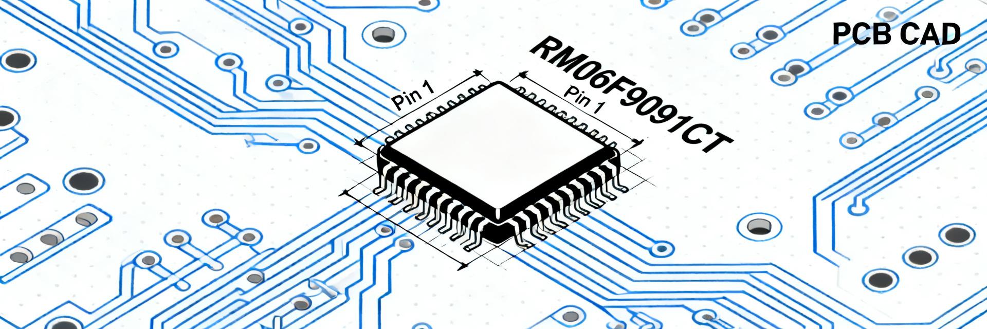
Evidence: Key fields to record from the manufacturer datasheet include pitch (3.00 mm), positions (8), current rating per pin (A), contact gender (male pin), contact material and plating (typical gold or tin finishes), rated voltage, pin dimensions, and mounting style (vertical SMT or through-hole).
Explanation: Capturing these fields in a standard table removes ambiguity for PCB layout, procurement, and mechanical integration; mismatches here drive most assembly failures.
| Parameter | Typical Value / Note |
|---|---|
| Pitch | 3.00 mm |
| Positions | 8 |
| Contact Gender | Male pins |
| Current Rating | Mid-power (Consult Datasheet) |
| Plating | Gold or tin options |
| Rated Voltage | Check insulation clearance |
| Mounting Styles | SMT / Through-hole |
Thermal, environmental ratings and compliance notes
Point: Thermal and compliance callouts determine assembly process limits and end‑use suitability.
Evidence: Important entries from the datasheet include operating/storage temperature ranges, flammability and glow-wire capability, typical reflow profile limits, and any ingress protection statements where applicable; generic compliance listings such as UL/CSA/IEC designations should be verified.
Explanation: Use a small matrix comparing temperature vs current to screen applications (e.g., continuous current at elevated ambient) and confirm reflow peak temperatures match your board assembly profile to avoid damage or loss of plating integrity.
Datasheet Deep-Dive — what to read first
Critical callouts every engineer must check
Point: Not all datasheet sections are equally urgent during initial design review.
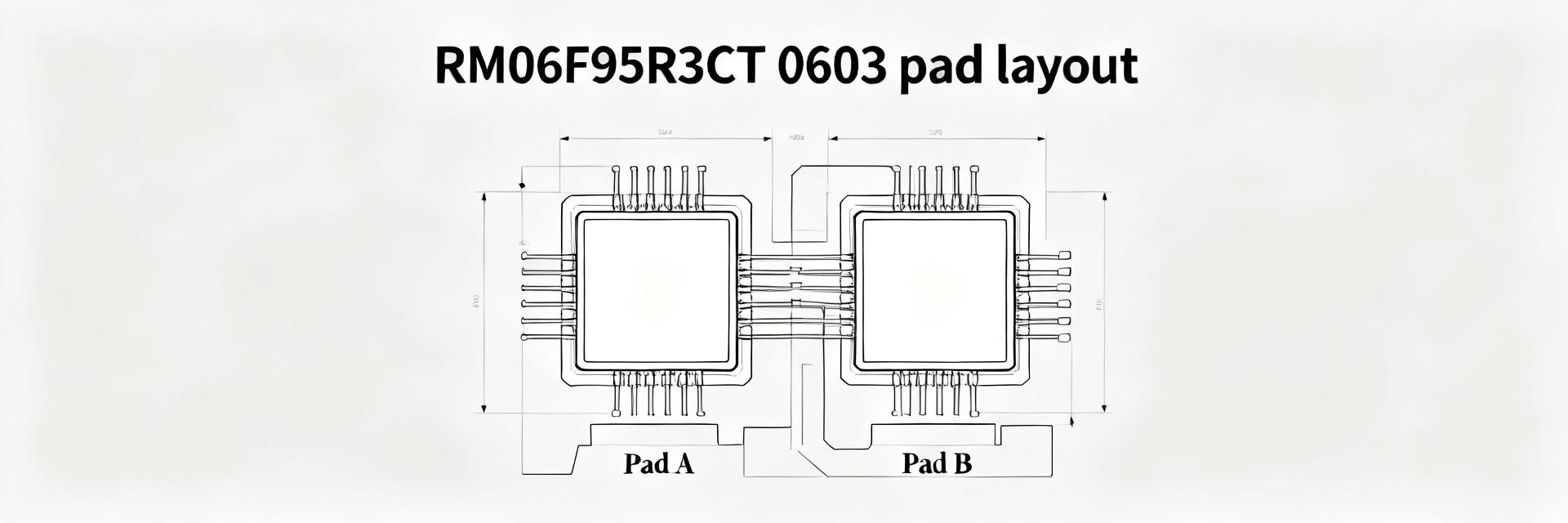
Evidence: Prioritize mechanical drawings (tolerances), recommended PCB land pattern, pin-out/numbering, material notes, soldering/reflow profile, and qualification/test procedures noted by the manufacturer/datasheet.
Explanation: Interpreting tolerance blocks and keep-out areas prevents footprint errors; for example, misreading seating plane tolerance can shift a row of pins out of spec and cause assembly stress or failed mating.
Extracts to convert into design assets
Point: Convert datasheet callouts into reusable CAD and process artifacts to streamline design handoffs.
Evidence: Create a PCB footprint (with reference to recommended land pattern), symbol library notes for schematic capture, pick-and-place orientation guidance, and a DFM checklist derived from the datasheet illustrations and tolerances.
Explanation: Annotated mechanical callouts and an attached checklist reduce iterations between ECAD and manufacturing—saving time and preventing mis-built prototypes.
Sourcing Landscape & Availability for 43045-0820
Application Examples & Design Considerations
Example A — Power Distribution
Layout and thermal strategy are key when distributing mid-level currents. Evidence: Use wider copper traces and thermal reliefs. Explanation: Measure contact resistance after thermal cycling to ensure long-term reliability.
Example B — Consumer Electronics
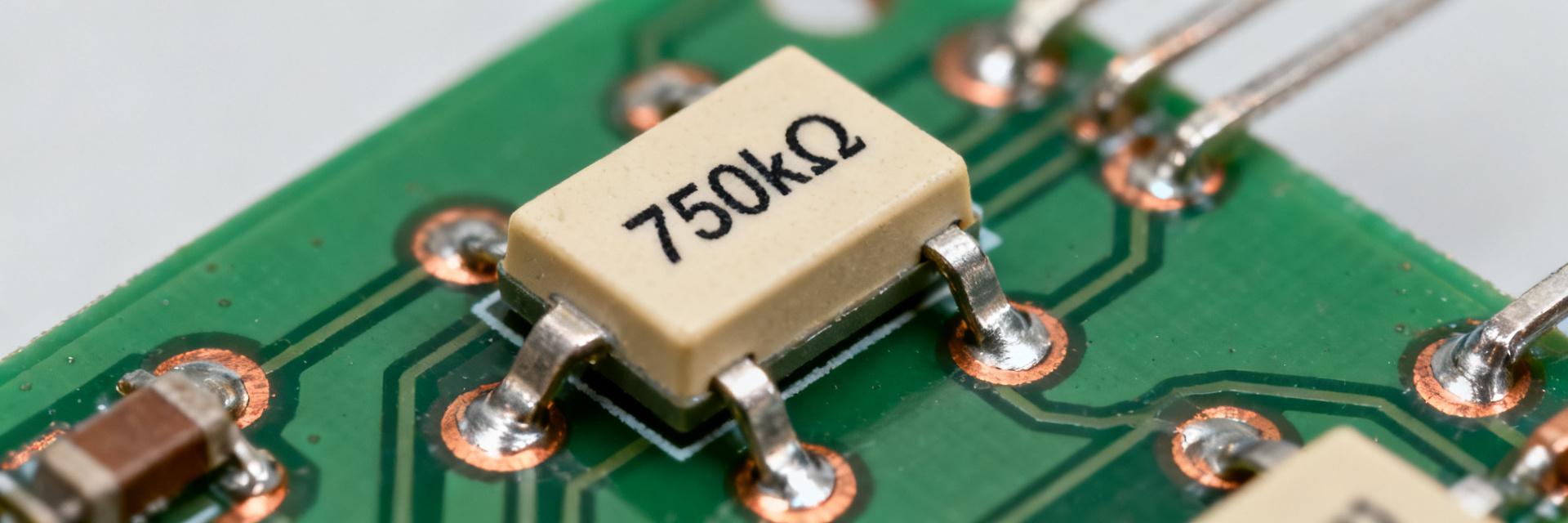
Trade-off favors low profile and reliable mating force. Evidence: Selection of gold plating for wear resistance. Explanation: Specify handling instructions to avoid bent pins during insertion operations.
Actionable Sourcing Checklist & Next Steps
Procurement checklist (ready-to-use)
- Confirm manufacturer datasheet revision and match to BOM
- Verify electrical and mechanical fit (pitch, pin dims, current rating)
- Confirm packaging type and reel orientation for assembly
- Request lot traceability and qualification documentation
- Confirm lead time, MOQ and any allocation policies
- Validate part with PCBA test sample before volume buy
Design → procure → validate workflow
Point: A staged workflow reduces rework risk and optimizes lead times.
Evidence: Recommended timeline: prototype sample order (small qty) → footprint and fit verification → pilot assembly → full PO with safety stock.
Explanation: Staggered deliveries and negotiated partial shipments help shorten effective lead-times while pilot assemblies uncover footprint or solderability issues early.