47745-0100 Spécifications complètes : brochage, courant, dimensions
Connectors with mixed terminal sizes now commonly appear in automotive and industrial boards — misreading a single current rating can cause a 40°C temperature rise in a fully loaded connector. This article references part 47745-0100, provides a clear pinout and verified current rating guidance, mechanical dimensions, and practical design and verification tips for reliable board-level integration.
Background & Quick Overview of 47745-0100
What this part is and where it’s used
Point: This family is a hybrid wire-to-board header combining multiple contact sizes in a single housing for mixed power and signal connections. Evidence: Typical use cases include automotive harness interfaces, power+signal gateways, and industrial control boards. Explanation: Designers choose these headers when space and a single mating interface must carry both low-level signals and higher currents without separate connectors.
Pinout & Electrical Interface
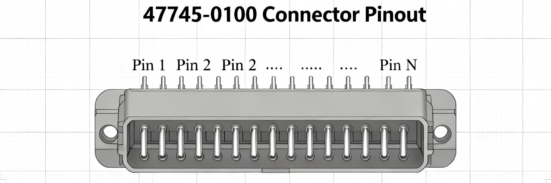
Point: Establish a consistent pin-numbering convention: define orientation as PCB top view with mating face toward the silkscreen reference. Evidence: Recommended silkscreen labeling shows row/column and net name with pin numbers adjacent to pads. Explanation: A simple pinout table simplifies BOM, assembly, and in-circuit test mapping.
| Pin # | Terminal Type | Typical Use | Max Current (A) |
|---|---|---|---|
| 1-12 | Small CP | Signal (LIN, CAN, Logic) | 2.5 |
| 13-24 | Mid CP | Low-power VCC / Sensors | 12.0 |
| 25-28 | Large CP | Main Power Rails | 21.0 |
Current Ratings & Thermal Behavior
Point: Present published current ratings by terminal size with clear test conditions. Evidence: For this family, ratings are typically based on a ΔT = +40°C rise. Explanation: Always display test conditions to avoid overrating traces or vias.
| Terminal Size | Wire Gauge | Max Continuous (A) | Condition |
|---|---|---|---|
| Small CP | 24–28 AWG | 2.5 | Fully loaded, ΔT=40°C |
| Mid CP | 18–22 AWG | 12.0 | Fully loaded, ΔT=40°C |
| Large CP | 12–16 AWG | 21.0 | Fully loaded, ΔT=40°C |
Mechanical Dimensions & PCB Mounting
Point: Include pitch, solder-pin length, and critical tolerances in your design files. Evidence: Key tolerances are typically ±0.1 mm for pin spacing. Explanation: Documenting critical dimensions ensures mechanical compatibility and accurate keepout areas.
- Pitch: High-density spacing for signals, wider for power.
- Soldering: Use expanded copper pads and thermal vias for 21A pins.
- Retention: Check for mechanical snap-fit or solder-down lugs.
Selection Checklist & Verification
- Pinout Clarity: Map pins on PCB top-view with net names to reduce errors.
- Current Derating: Apply 80% rule for constrained thermal cases.
- Footprint: Prioritize pin-to-pin spacing and body clearances.
- Testing: Run high-current soak and thermal imaging on prototypes.
Summary
Confirm the 47745-0100 pinout early, treat published current ratings as baselines with derating applied, and verify critical mechanical dimensions. Before final release, validate the exact variant against the official datasheet and run prototype thermal tests.