IKCM30F60GA IPM Module: Full Specs & Performance Report
Benchmarks for 600 V / 30 A-class IPM modules show wide variance in switching loss and thermal resistance — understanding the IKCM30F60GA real-world numbers is critical for robust motor-drive designs. This report consolidates datasheet specs, representative bench metrics, and practical integration guidance for US hardware engineers, focusing on measurable specs, switching losses, thermal resistance estimation, and PCB/EMI trade-offs for production-ready motor drives.
1 — Quick Technical Snapshot & Key Specs
1.1 Core electrical specs to list
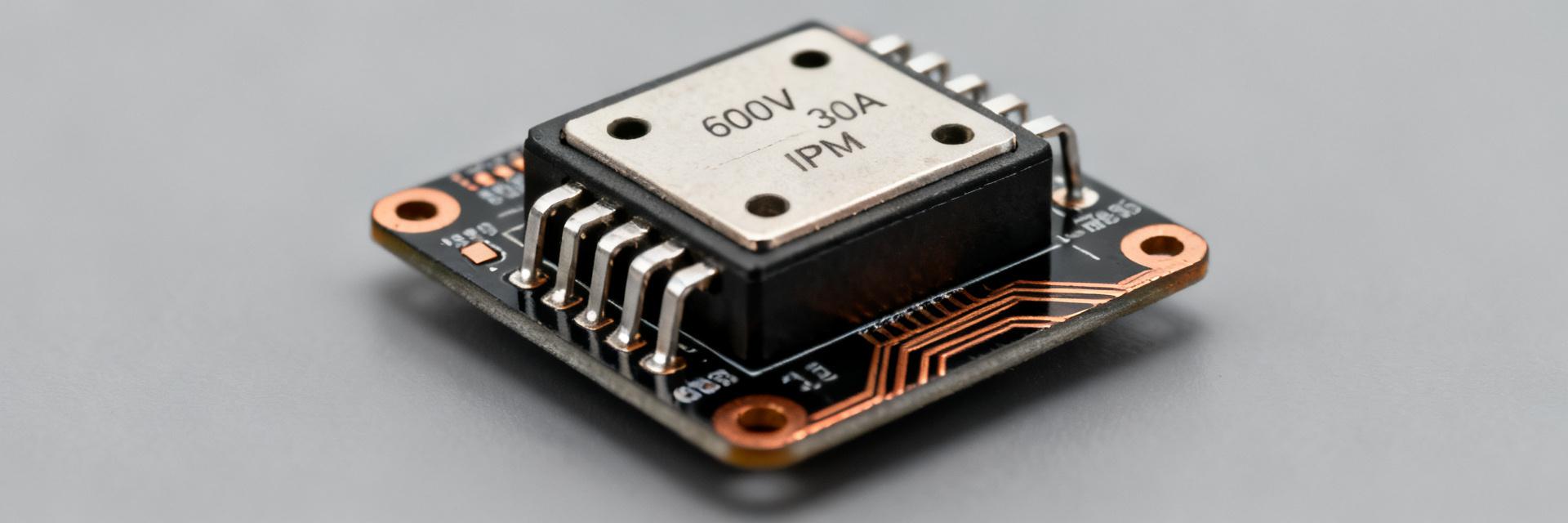
Point: The module targets three-phase inverter roles with 600 V blocking and ~30 A continuous capability. Evidence: Manufacturer-stated ratings and typical test conditions indicate DC link up to 600 V and continuous current near the 30 A class; note rated ambient and cooling assumptions. Explanation: Verify continuous current under your cooling strategy because datasheet specs assume specific junction-to-case and case-to-ambient conditions; treat peak pulsed currents conservatively.
1.2 Protection & functional feature summary
Point: Integrated protections simplify drive design. Evidence: The module includes built-in overcurrent detection, undervoltage lockout, and thermal-shutdown flags as part of the driver block. Explanation: These features reduce external component count but require verification of diagnostic thresholds on the bench since trip timing and hysteresis affect motor-fault handling and system recovery strategies.
2 — Electrical Performance Deep-Dive
2.1 Static and dynamic losses (conduction & switching)
Point: Conduction and switching losses dominate efficiency in 30 A-class IPMs. Evidence: On-state voltage drop and diode forward drop define conduction loss; Eon/Eoff figures in the datasheet provide switching-energy baselines measured at specific Vdc, current, and gate-drive. Explanation: Bench-measure switching losses at your expected Vdc and current—example conditions: 200 Vdc, 10–20 A, 25–50 kHz PWM—to capture real Eon/Eoff and compute total power dissipation for thermal budgeting.
| Parameter | Datasheet | Bench (suggested) |
|---|---|---|
| Vce(on) / Rds-eq | datasheet typical | measure at 10 A, 25°C |
| Eon / Eoff | given at 200 V, 10 A | measure at 200 Vdc, 10–20 A |
| Diode Vf | specified typ. | pulse test at rated current |
2.2 Gate-driver behaviour & switching waveforms
Point: Gate drive tuning determines EMI and switching loss trade-offs. Evidence: Expected gate thresholds and Miller plateau characteristics require observing Vgs, Vds, and Id under switching transients. Explanation: Use a 100 MHz oscilloscope with proper grounding to capture waveforms; try gate resistors from low to moderate values and log rise/fall times, overshoot, and dv/dt to balance losses versus ringing and EMI.
3 — Thermal Performance & Reliability
3.1 Thermal resistance, junction-to-case and case-to-ambient
Point: Thermal resistance values drive heat-sink and PCB requirements. Evidence: Datasheet lists Rth(j‑c) and Rth(j‑a) under defined mounting and airflow; use those as baselines but expect higher real-world Rth(j‑a) without ideal heat-sinking. Explanation: Estimate Tj = Ta + Pd*(Rth(j‑c)+Rth(c‑a)); validate with thermocouple on case and junction estimation from electrical test to confirm headroom under continuous load.
| Thermal Calc Inputs | Example Value |
|---|---|
| Ambient Ta | 40°C |
| Estimated Pd (loss) | 12 W |
| Rth (j‑a) assumed | 4.0 °C/W |
| Resulting ΔTj | 48 °C → Tj ≈ 88 °C |
3.2 Long-term reliability factors and derating
Point: Operational derating extends life and prevents substrate or bond-wire failure. Evidence: Repeated thermal cycling and high junction temperatures accelerate solder fatigue and wire-bond creep. Explanation: Adopt conservative derating (for example 70–80% of continuous current at target ambient) and run accelerated tests—thermal cycling 100–1000 cycles and extended high-temperature storage—to validate lifetime for intended duty cycles.
4 — Integration & PCB Design Guide
4.1 PCB layout, grounding, and decoupling best practices
Point: Layout and copper area critically influence thermal and electrical performance. Evidence: Large thermal pad, wide low-inductance power planes, and proximity of decoupling capacitors are common datasheet recommendations. Explanation: Route high-current loops with thick short traces, place bootstrap and decoupling caps within millimeters of driver pins, and provide a solid thermal via array under the module mounting pad to lower case-to-board resistance.
4.2 EMI mitigation, snubbing and gate-drive tuning
Point: Snubbers and gate resistors reduce ringing at the cost of extra loss. Evidence: RC or RCD snubbers clamp Vds overshoot; increased gate resistance slows edges and lowers EMI. Explanation: Start with conservative gate resistance, measure conducted emissions at key test points, and add RCD snubbers or common-mode filters selectively; tune to meet EMI limits while tracking added switching loss in thermal budget.
5 — Application Cases & Comparative Notes
5.1 Typical use cases and suitability
Point: The module fits three-phase motor drives in HVAC, appliances, and industrial micro-drives. Evidence: 600 V blocking and 30 A-class current suit motors with moderate duty cycles and good cooling. Explanation: For steady torque applications expect lower switching frequency and simpler cooling; for high-frequency, high-dynamic torque profiles validate switching losses and upgrade thermal management accordingly.
5.2 How it compares to peer-class IPM modules
Point: Comparison centers on protection suite, thermal handling, and footprint. Evidence: Peer 600 V / 30 A IPMs vary in Rth(j‑a), diagnostic outputs, and package thermal vias. Explanation: Choose this module when integrated protections and moderate footprint win over maximum thermal headroom; opt for alternatives when aggressive thermal dissipation or higher switching-efficiency is the primary constraint.
6 — Testing Checklist & Procurement Considerations
6.1 Pre-deployment test checklist
Point: A focused test sequence uncovers integration issues early. Evidence: Gate-driver validation, short-circuit trip testing, thermal ramp, and EMI scans address common failure modes. Explanation: Run step tests: validate logic-level inputs and bootstrap behavior, confirm OCP timing with controlled faults, perform thermal soak at rated load, and capture switching waveforms and emissions to defined pass/fail criteria.
6.2 Sourcing, part verification, and lifecycle notes
Point: Verify part markings and sample sufficient units for validation; the IKCM30F60GA should be inspected on receipt. Evidence: Counterfeit or mis-marked modules can fail early; packaging and lot codes help traceability. Explanation: Procure engineering samples for full-characterization, keep traceable lot records, and plan for lifecycle risk by qualifying alternates and requesting long-lead samples for production ramp.
Summary
- IKCM30F60GA offers a solid balance of integrated protections and 600 V / ~30 A specs for three‑phase motor drives; validate switching losses at your operating Vdc to size cooling and avoid hot‑spot thermal stress.
- Implement PCB thermal pads, thermal vias, and a heat-sink plan to meet Rth(j‑a) targets; account for realistic case-to-ambient resistance in thermal calculations and design margins accordingly.
- Run the outlined pre-deployment tests: gate-drive, controlled OCP, thermal soak, and EMI scans; use results to tune gate resistors, snubbers, and decoupling to balance loss versus EMI.
Frequently Asked Questions
How does IKCM30F60GA compare in switching losses to similar 600 V IPM modules?
Switching loss depends on Vdc, current, and gate-drive. Typical datasheet Eon/Eoff provide baselines at defined conditions; expect measured switching losses to be 10–30% higher in real layouts. Always bench-measure at your Vdc and current profile to quantify losses and update thermal budget and cooling strategy accordingly.
What thermal resistance values should be used for IKCM30F60GA thermal design?
Use the datasheet Rth(j‑c) as a starting point and treat Rth(j‑a) as optimistic unless you replicate the specified mounting and airflow. Add PCB and TIM resistance estimates, and validate with thermocouple readings during an extended load test to refine junction temperature estimates for continuous operation.
Which pre-deployment tests are essential for IKCM30F60GA integration?
Essential tests include gate-drive validation (logic thresholds and bootstrap checks), controlled short-circuit/OCP timing, extended thermal soak at target load, switching waveform capture for EMI/ringing, and conducted emissions scans. Define pass/fail thresholds ahead of testing and iterate gate-drive/snubber choices based on measured results.
What are the key PCB layout guidelines for the IKCM30F60GA to optimize EMI?
Key guidelines include routing high-current loops with thick, short traces to minimize parasitic inductance, placing bootstrap and decoupling capacitors within millimeters of driver pins, and introducing a solid thermal via array under the module mounting pad to decrease thermal resistance while maintaining single-point ground configurations to shield noise.