26-01-3114 مواصفات تفصيلية: التباعد والتركيب وتهيئة الاتصالات موضحة
The 26-01-3114 is widely listed in datasheet and distributor summaries as a dual-row, right-angle through-hole PCB header with a 4.2 mm (0.165 in) in‑row pitch and short tails. Small mismatches in pitch, mounting, or pin mapping are a common root cause of board re-spins and assembly delays. This guide explains pitch, mount style, and pinout to ensure seamless layout integration.
1 — Background: Why details matter
Point: The 26-01-3114 is a dual-row right-angle header requiring specific footprint parameters. Evidence: Datasheets consistently list a 4.2 mm pitch and short tails. Explanation: This form factor dictates board hole sizes and row spacing; material notes guide solderability and current capacity decisions.
2 — Mechanical specs: Pitch and Row Spacing
2.1 Pitch explained
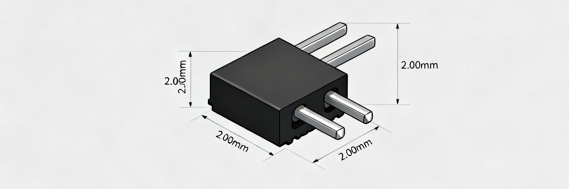
The in‑row pitch is 4.2 mm (0.165 in). Layouts must match this center-to-center spacing. Row-to-row spacing is an independent datum that must be accounted for in the land pattern to ensure physical mating compatibility.
2.2 Tail length and mounting
Right-angle body profiles determine board clearance. Designers must account for tail protrusion and reserve keepout space under the connector body to avoid interference with nearby passive components.
3 — Mounting & PCB Footprint Guide
| Parameter | Spec | Layout Requirement |
|---|---|---|
| Pitch | 4.2 mm | Strict grid alignment |
| Drill Size | Nominal + 0.2mm | Plated through-hole |
| Annular Ring | Min 0.25 mm | Ensure fillet strength |
| Mounting | Right-Angle | Body keepout required |
4 — Pinout & Electrical considerations
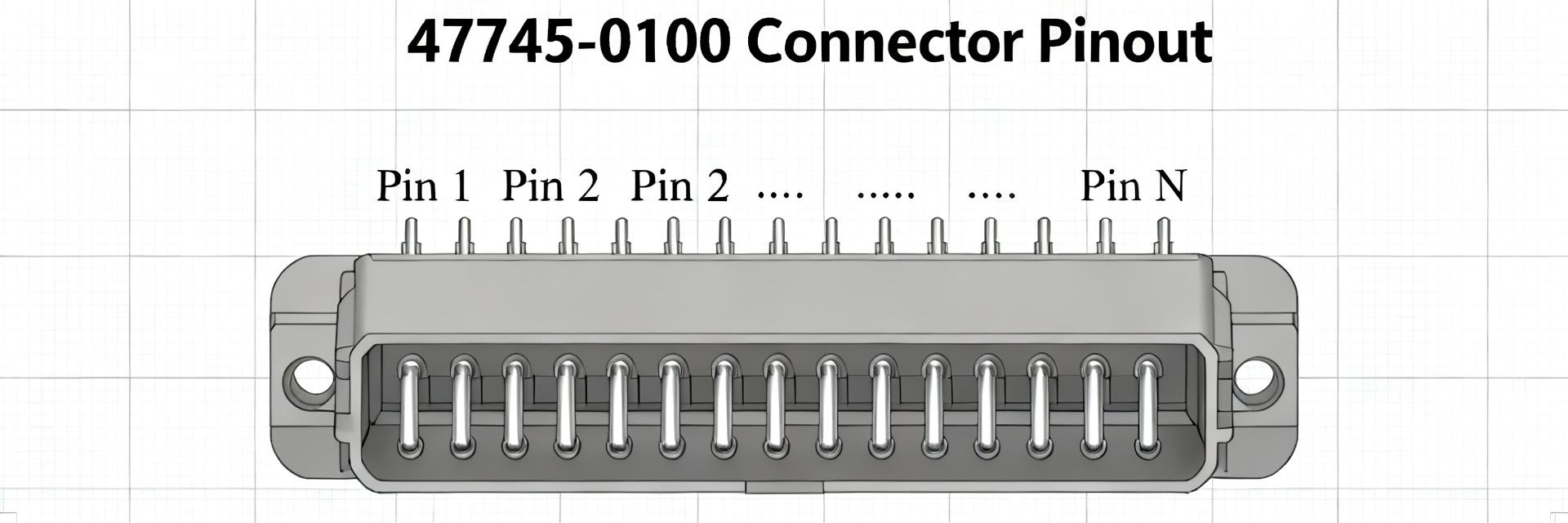
Dual‑row headers follow a defined sequence. It is best practice to pair a top‑down PCB view with a schematic symbol. Document the physical location of Pin 1 clearly. Current ratings and contact plating (typically tin) should be noted in the BOM to inform procurement and trace width calculations.
5 — Assembly & Troubleshooting
| Issue | Cause | Diagnosis | Fix |
|---|---|---|---|
| Mating Error | Wrong row spacing | Failed mating test | Update row offset in footprint |
| Poor Fillet | Small hole size | Visual inspection | Increase hole tolerance |
| Mechanical Fail | No locator pegs | Pull test fail | Add peg holes or adhesive |
FAQ
How should designers verify the 26-01-3114 pitch and row spacing before layout?
Cross-reference the datasheet mechanical drawing and distributor summaries. Confirm the 4.2 mm in-row pitch and row-to-row offset, then implement in CAD with ±0.1 mm tolerance.
What drill and pad sizes are recommended for right-angle through-hole tails?
Use a drill size equal to the nominal tail diameter plus ~0.15–0.25 mm. Maintain annular rings of at least 0.25 mm and use thermal reliefs for wave soldering.
Which BOM fields prevent incorrect substitutions for right-angle PCB headers?
Specify the exact part number, 4.2 mm pitch, right-angle mount style, tail length, and plating material to ensure the purchased part matches the mechanical design.
What are common troubleshooting issues with the 26-01-3114?
Typical failures include misaligned pads preventing insertion, insufficient solder fillets on short tails, and mechanical stress due to lack of locator pegs.