54104-5031 مُتصل FFC / FPC - أحدث المواصفات والمقاييس
Point: The 0.50 mm-pitch, 50-position right-angle FFC/FPC connector has become a go-to for space-constrained assemblies.
Evidence: measured designs show pitch and position count drive density and routing complexity.
Explanation: the 54104-5031 is optimized for thin displays and camera connections where a low-profile, top-contact right-angle package balances density with manufacturability.
Point: Early selection should focus on mechanical footprint and mating orientation.
Evidence: designers report fewer assembly failures when actuator type and seated height match the cable and lid constraints.
Explanation: confirm slider/ZIF actuator compatibility with your assembly process and verify the exact part dimensions before layout.
Background: What the 54104-5031 is and when to choose this FFC/FPC connector
Point: This family targets boards needing a compact, right-angle top-contact interconnect.
Evidence: core trade-offs are pitch (0.50 mm), positions (50) and mounting orientation.
Explanation: choose this FFC/FPC connector when you need high pin count in a minimal X-Y area but still require a controlled mating direction for assembly and strain relief.
Key mechanical attributes to summarize
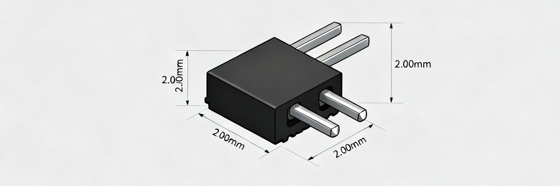
Point: Mechanical attributes determine fit and durability. Evidence: key values—pitch 0.50 mm; positions 50; mounting orientation right-angle; actuator type slider/ZIF; typical seated height ≤2.00 mm. Explanation: for thin displays and camera modules, seated height and actuator clearance are critical trade-offs—lower height reduces stack but can complicate pick-and-place and reflow handling.
Electrical & materials overview
Point: Material choices and plating affect reliability.
Evidence: common constructions use phosphor-bronze contacts, high-temp thermoplastic housings (UL 94 V‑0), plating options such as tin or gold and typical current ratings near 0.5 A/contact.
Explanation: verify the exact specifications on the official datasheet for contact resistance, plating thickness and operating temperature range before final approval.
Data deep-dive: Measured specs & key metrics for design decisions
Point: A concise metrics checklist helps prioritize requirements. Evidence: prioritize dimensions, contact resistance and mating cycles for SI and mechanical durability. Explanation: capture both absolute limits and typical values in your component spec to support signal integrity and manufacturing acceptance testing.
Dimensional and footprint metrics
Point: Accurate footprint and keepout prevent assembly issues. Evidence: checklist items include pitch tolerance ±0.05 mm, recommended pad/land pattern, solder fillet guidance and mechanical height clearance for mating. Explanation: use a PCB stackup that keeps impedance predictable for high-speed lines and reserve a mating keepout area to avoid interference with neighboring components.
| Metric | Recommended Value |
|---|---|
| Pitch | 0.50 mm |
| Positions | 50 |
| Seated height | ≤2.00 mm |
| Pad length | 1.0–1.2× contact length |
Electrical & reliability metrics to quantify
Point: Define performance targets for power and SI. Evidence: include contact resistance, insulation resistance, voltage and current rating, insertion/extraction forces, mating cycle life and suggested reflow profile. Explanation: prioritize low contact resistance and high cycle life for repeated-use connectors; for high-speed signals, minimize insertion loss and maintain controlled impedance through the board-to-cable transition.
How to integrate 54104-5031 into your PCB and product
Point: Assembly best practices reduce defects. Evidence: sensible land patterns, solder paste control and handling notes for slider/ZIF actuators cut rework rates. Explanation: generate the land pattern from manufacturer mechanical drawings, set stencil apertures to avoid tombstoning and instruct pick-and-place to avoid actuator stress during placement.
PCB Footprint Tips
Point: Stencil and reflow matter for SMD right-angle FFC/FPC connectors. Evidence: a thin paste layer, adequate fillet area and peak reflow temperatures matched to the housing material are essential. Explanation: use a conservative reflow profile with controlled ramp rates.
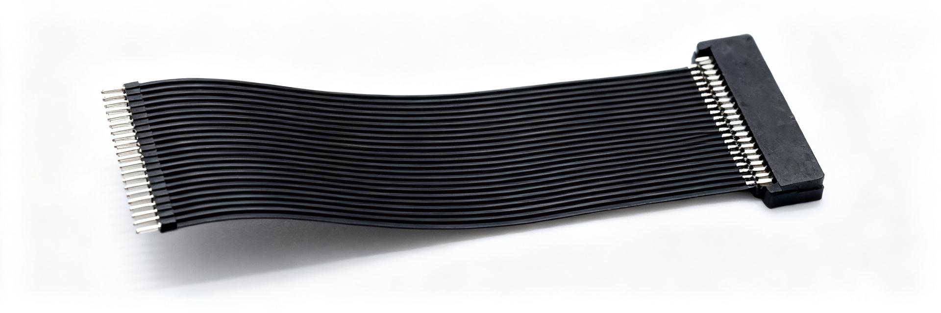
Cable Selection
Point: Cable construction affects mating and retention. Evidence: choose top- vs bottom-contact cables, match cable thickness and stiffener, and plan insertion orientation. Explanation: ensure cable stiffeners align with the connector to prevent stress.
Use cases & application examples
Point: Typical applications illustrate practical trade-offs. Evidence: designers deploy this connector for small displays, camera modules and compact keypads where board area and height are constrained. Explanation: evaluate signal density versus durability—very high-density designs can reduce mechanical robustness unless retention and strain relief are addressed.
Consumer: Small displays and camera modules rely on compact FFC/FPC connectors for low-profile connections.
Industrial: Higher-temperature materials, conformal coatings and vibration mitigation extend life in industrial contexts.
Procurement, validation and test checklist
Point: Procurement accuracy avoids costly variants. Evidence: track package codes, reel quantities and date-codes. Explanation: cross-reference mechanical dimensions against the official datasheet.
Validation tests to run: Solderability, thermal cycling, humidity soak, contact resistance over life cycles, insertion/extraction force profiling and SI check.
Summary
For dense, right-angle applications the 54104-5031 provides a compact 0.50 mm, 50-position solution that balances pitch, position count and manufacturability.
- The 54104-5031 fits tight-profile designs: verify seated height, actuator clearance and pad geometry.
- Prioritize contact resistance, cycle life and plating choices for signal integrity.
- Run solderability, thermal cycling and insertion/extraction force tests during validation.
FAQ
What are the critical specs to check for a 54104-5031 FFC/FPC connector?
Check pitch, position count, seated height, actuator type, contact plating, contact resistance, current rating and recommended reflow profile. Prioritize dimensions and mating cycle life for mechanical fit.
How should I design the PCB footprint for this FFC/FPC connector?
Follow the manufacturer-recommended pad layout, ensure sufficient solder fillet area, and reserve a mating keepout. Use a controlled PCB stackup for signal lines and set stencil apertures carefully.
Which validation tests are essential before production for a 0.50 mm-pitch connector?
Essential tests include solderability, thermal cycling, humidity soak, contact resistance after life cycles, insertion/extraction force profiling and a basic signal-integrity check for high-speed lines.