RM06F7R15CT SMD 저항기: 전체 사양 및 패드 가이드
Compact SMD parts and correct land patterns are among the leading PCB failure and rework drivers in modern high-density assemblies. Accurate datasheet-derived footprints reduce tombstoning, thermal stress, and assembly reflow defects. Consolidating the RM06F7R15CT electrical and mechanical specs with a ready-to-implement footprint helps engineering teams cut rework and accelerate first-pass yield.
Product background: Why choose RM06F7R15CT
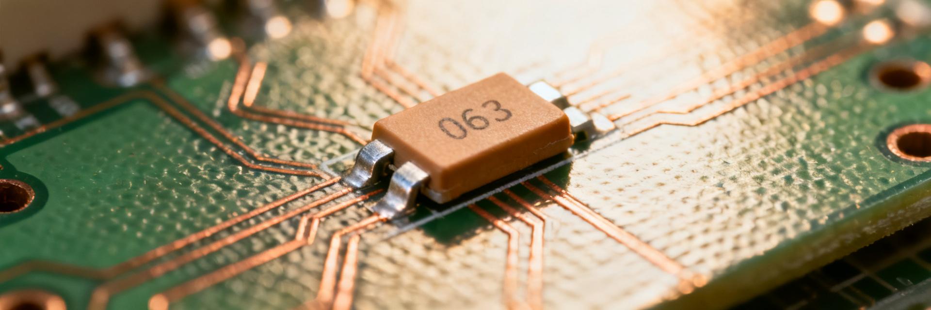
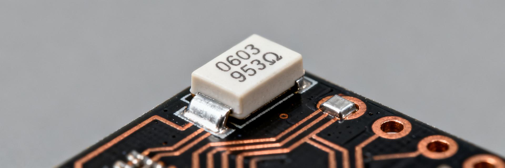
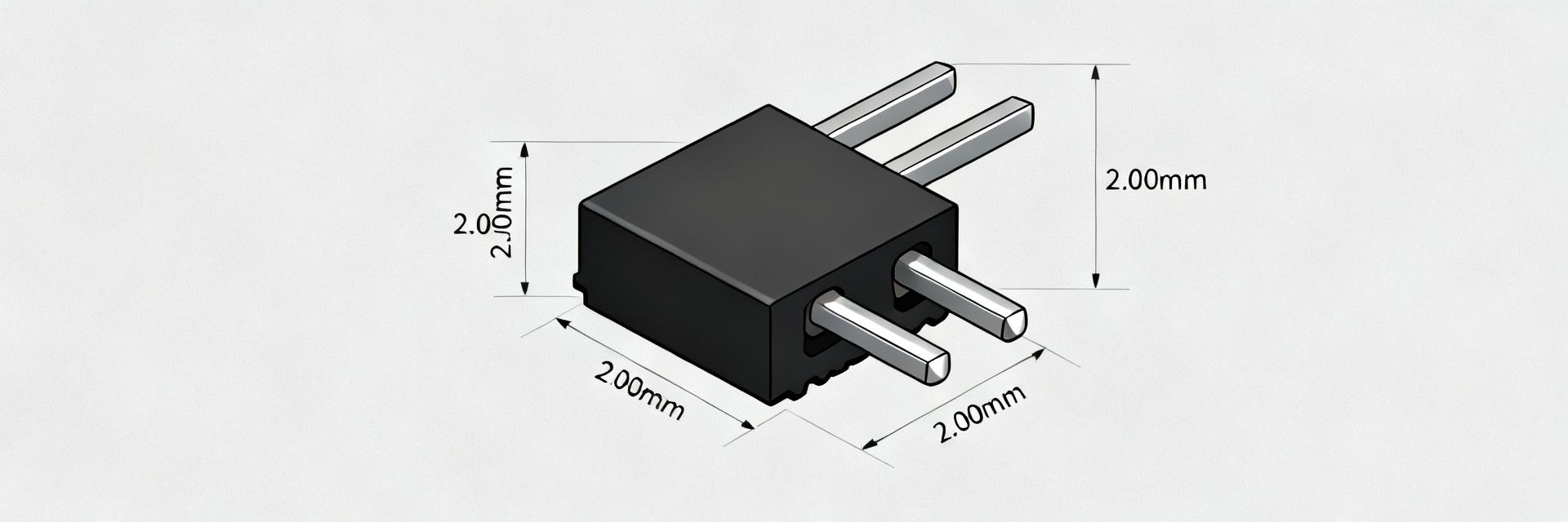
The RM06F7R15CT is an 0603-class SMD Resistor utilizing thick-film technology. Designers select this specific part for its balance of cost-efficiency and precision (1% tolerance) in space-constrained environments.
| Parameter | Specification (RM06F7R15CT) |
|---|---|
| Case Size | 0603 (1608 Metric) |
| Resistance | 7.15 Ω |
| Tolerance | ±1% (F) |
| Power Rating | 0.1W (1/10W) @ 70°C |
| TCR | ±100 ppm/°C |
| Operating Temp | -55°C to +155°C |
RM06F7R15CT Footprint & Land-Pattern Guide
Recommended Dimensions
For standard high-reliability assembly, the following land pattern dimensions are recommended for the 0603 package:
- Pad Width: 0.95 mm
- Pad Length: 1.00 mm
- Gap (S): 0.70 mm
- Overall Span: 2.70 mm
Assembly & Reflow Profile
Follow a lead-free SAC305 reflow profile with a peak temperature of 245°C - 260°C. To prevent tombstoning (the "Manhattan effect"), ensure that both pads have symmetrical thermal relief when connected to internal planes.
Industrial Design Checklist
- ✔ Verify 1% tolerance requirement for 7.15Ω signal path.
- ✔ Confirm 0.1W power rating is sufficient for peak DC bias.
- ✔ Check Solder Mask expansion (typically 0.05mm per side).
- ✔ Validate 0603 footprint against pick-and-place nozzle clearance.
Frequently Asked Questions
How do I verify RM06F7R15CT power derating for my board?
Compare the datasheet rated power (0.1W at 70°C) with your board thermal environment. Calculate derating based on copper area and ambient temperature; if power dissipation approaches rating, increase copper heatsinking or transition to a larger 0805 package.
What paste mask settings work best for RM06F7R15CT 0603 footprint?
Start with 60–80% paste aperture coverage per pad using a 0.10–0.12 mm stencil. Rectangular apertures matching the pad shape reduce skew. Tune paste volume empirically on sample boards to minimize tombstoning.
Which inspection checks should confirm a correct RM06F7R15CT assembly?
AOI targets should include proper pad wetting, symmetric fillets, no tombstoning, and correct part orientation. Visual criteria include continuous fillets and the absence of solder beads or delamination around the 0603 body.
When should I choose RM06F7R15CT over other 0603 resistors?
Select RM06F7R15CT when specific 7.15 ohm precision (1%) is required in a compact 0603 form factor. It is ideal for shunt sensing, precision pull-ups, or analog signal conditioning where TCR stability (100ppm) is vital.