0603 887 ohm resistor specs: concise performance report
A technical guide to performance benchmarks, datasheet verification, and board-level implementation for 887 Ω SMD components.
The 0603 (1608 Metric) chip resistors remain a dominant SMD footprint for compact consumer and industrial PCBs. The 887 ohm nominal value is widely offered in 1% and 5% tolerances with typical 100 mW (1/10 W) ratings. This report focuses on the 0603 887 ohm resistor, outlining datasheet verification, practical performance expectations, and bench checks to confirm reliability.
Background: 0603 887 Ohm Resistor Snapshot
Footprint & Physical Dimensions
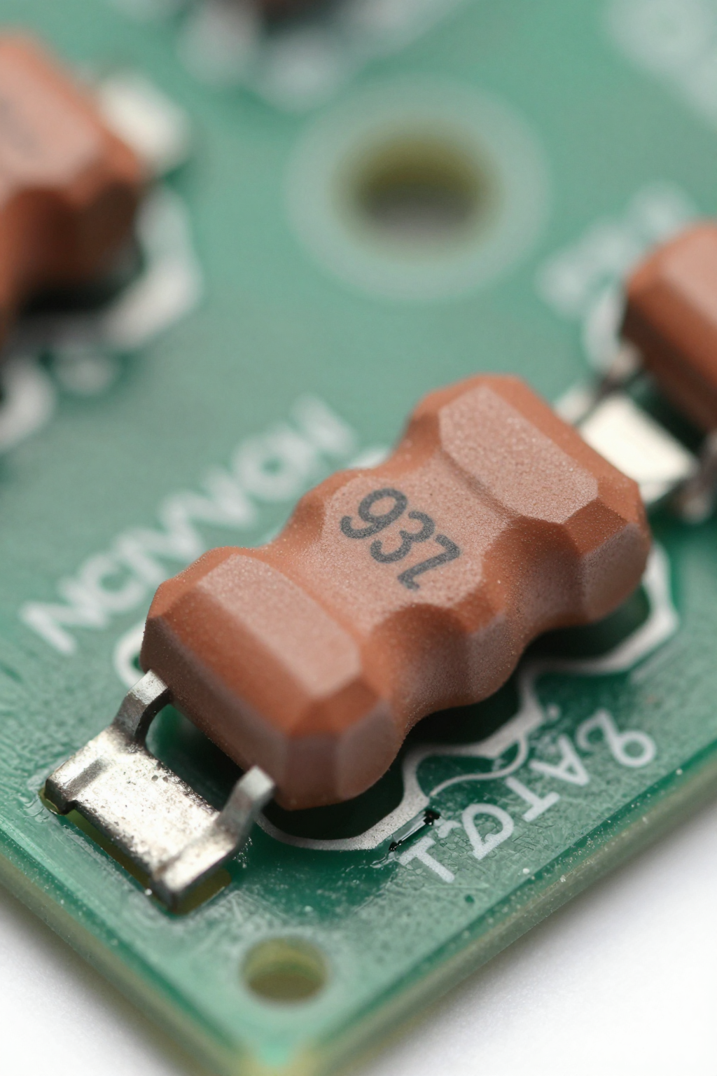
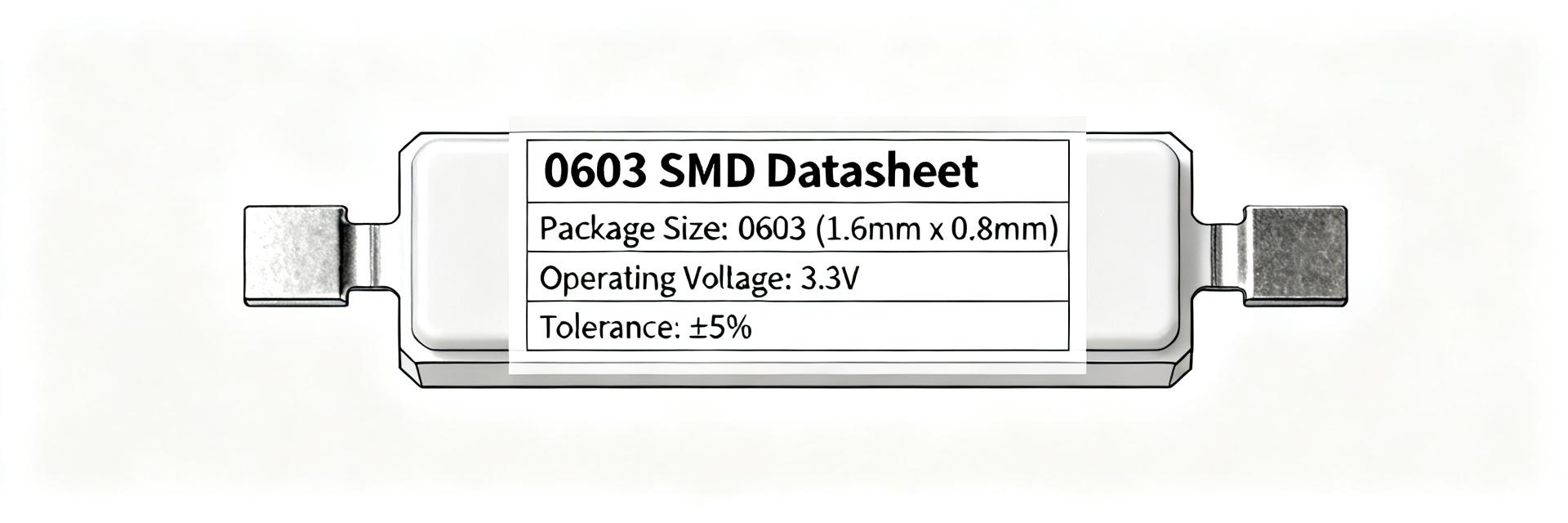
A 0603 footprint denotes a nominal imperial size of 0.06" × 0.03" (1.6 mm × 0.8 mm), with a typical seated height of 0.25–0.55 mm. IPC-7351 recommendations specify pad geometries to avoid "tombstoning" and ensure consistent solder fillets.
Nominal Electrical Parameters
Standard listings for an 887 Ω part show ±1% or ±5% tolerance and ~100 mW continuous power. Technology matters: thick-film (50–200 ppm/°C) vs. thin-film (5–50 ppm/°C). Power rating and TCR (Temperature Coefficient of Resistance) are primary selection criteria.

Key Specifications to Verify
Tolerance & TCR
Tolerance drives absolute accuracy while TCR dictates temperature drift. For analog precision, search for "0603 887 ohm resistor tolerance TCR" and aim for ≤50 ppm/°C.
Power & Derating
While rated at 100 mW, actual performance depends on the derating curve. Verify maximum operating temperatures, typically −55°C to +155°C.
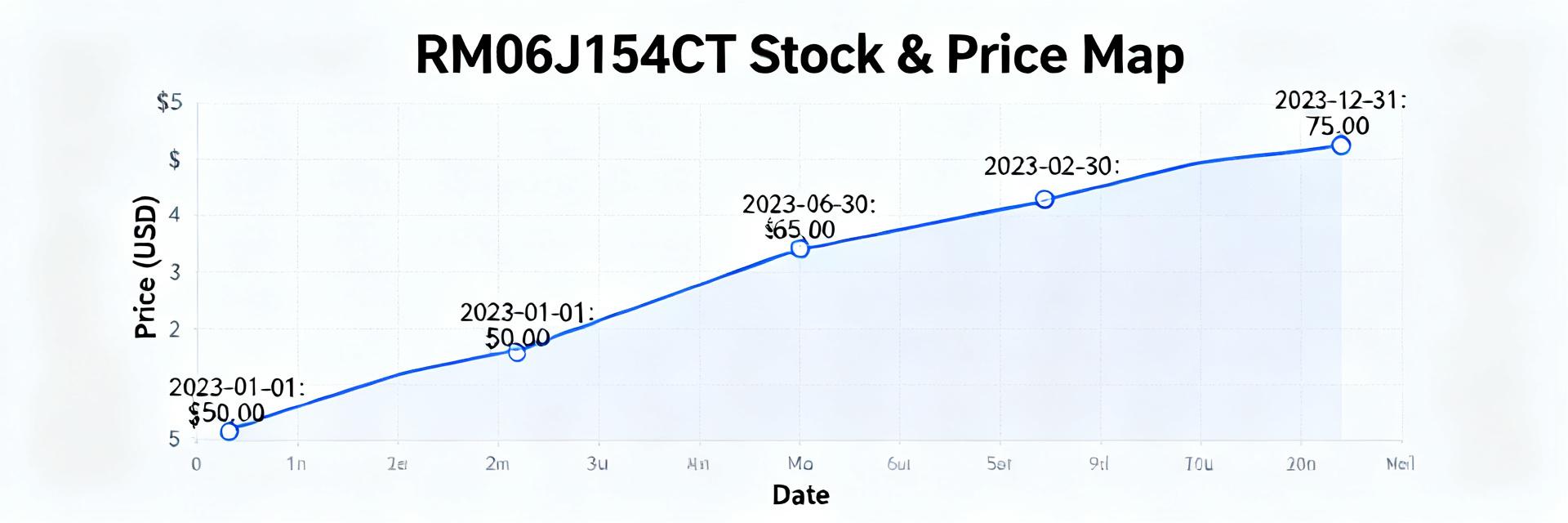
Visualized Derating Guidance
Performance Characteristics
Noise & Stability
Thick-film variants show higher noise. Run DC aging and humidity soak tests to quantify drift. Expect drift in the tens to hundreds of ppm initially for thick-film components.
Transient Response
Pulse capability exceeds continuous rating but requires duty-cycle limits (e.g., 10% duty, 10 ms width). Monitor Delta-R during bench-test pulses to validate board thermal impedance.
Selection & PCB Design Guidance
- ✔ Package Strategy: Pick 0603 when space is the priority. If power margin is
- ✔ Thermal Layout: Use recommended pad patterns; avoid overly large copper connections without thermal relief to maintain soldering quality.
- ✔ Soldering: Follow reflow profiles in the specifications datasheet; consider copper pours for heat spreading on high-density boards.
Precision Divider Network
In divider circuits, 887 Ω tolerance affects output error directly. For sub-0.1% targets, substitute 1% thick-film with 0.1% thin-film parts to minimize TCR-derived drift.
Signal Conditioning
Locate resistors close to amplifier inputs. Avoid high-impedance nodes exposed to EMI. Use single-point grounding to mitigate noise coupling in small-signal paths.
Practical Checklist & Troubleshooting
Pre-Order Specs
- Confirm Part Number, footprint (0603), and Tolerance.
- Verify TCR and load-life data in the datasheet.
- Check RoHS compliance and reel packaging specs.
On-Board Diagnosis
- Measure in-circuit resistance for
- Use thermal imaging to detect hotspots (>10°C rise).
- Inspect for solder fillets or mechanical cracking.