48074-9101 Datasheet Deep-Dive: Specs, Pinout & Tests
Modular RJ connectors remain a dominant choice in low-voltage network and embedded designs, accounting for a substantial share of board-level connectors used in 10/100 Ethernet and embedded I/O.
A precise read of the 48074-9101 datasheet matters because small variances in contact resistance, insulation ratings, or footprint geometry directly influence board reliability and EMC performance. This article covers the datasheet essentials: electrical specs, a complete pinout, recommended bench and environmental tests, PCB integration tips, and practical troubleshooting steps.
How to Read the 48074-9101 Datasheet (Background)
Datasheet sections to prioritize
Point: Start by scanning the part summary and ordering information to confirm mechanical variant and mounting style.
Evidence: Next prioritize electrical ratings, pinout/footprint, mechanical drawings, materials & finishes, packaging, and test/qualification notes.
Explanation: A quick-check checklist should verify rated voltage/current, mounting orientation (right-angle vs. vertical), presence of LEDs or magnetics, and recommended PCB thickness before advancing to layout or procurement.
Key terms, units, and tolerances explained
Point: Common datasheet terms—rated current, contact resistance, dielectric withstanding voltage, insulation resistance, and operating temperature—govern safe operating envelopes.
Evidence: Tolerances on dimensions (±0.1 mm typical) and electrical limits dictate mechanical clearance and safety margins.
Explanation: Convert units to US customary where needed, derate currents by 20–30% for continuous operation, and apply tolerance stacks when checking mechanical fit against the PCB assembly.
Key Electrical Specs & Performance of 48074-9101 (Data analysis)
Voltage, current, and signal characteristics
Point: Validate the connector's rated voltage and current and its suitability for 10/100 Base-T signaling. Evidence: Typical contact resistance and insertion loss figures in the datasheet set pass/fail thresholds. Explanation: Use the datasheet limits to set electrical tests—e.g., maximum contact resistance per contact and a safety margin (20–30%) for pass/fail—so link reliability and SI headroom are maintained.
Integrated features affecting electrical behavior
Point: Note any integrated magnetics, LEDs, or shielding that change pin assignments or grounding needs. Evidence: Datasheet lines for magnetics and LED drive characteristics define isolation and current requirements. Explanation: Confirm which pins are tied to magnetics or LED drivers, how shield tabs connect to chassis or board ground.
Mechanical Details & Pinout Breakdown for 48074-9101 (Data analysis)
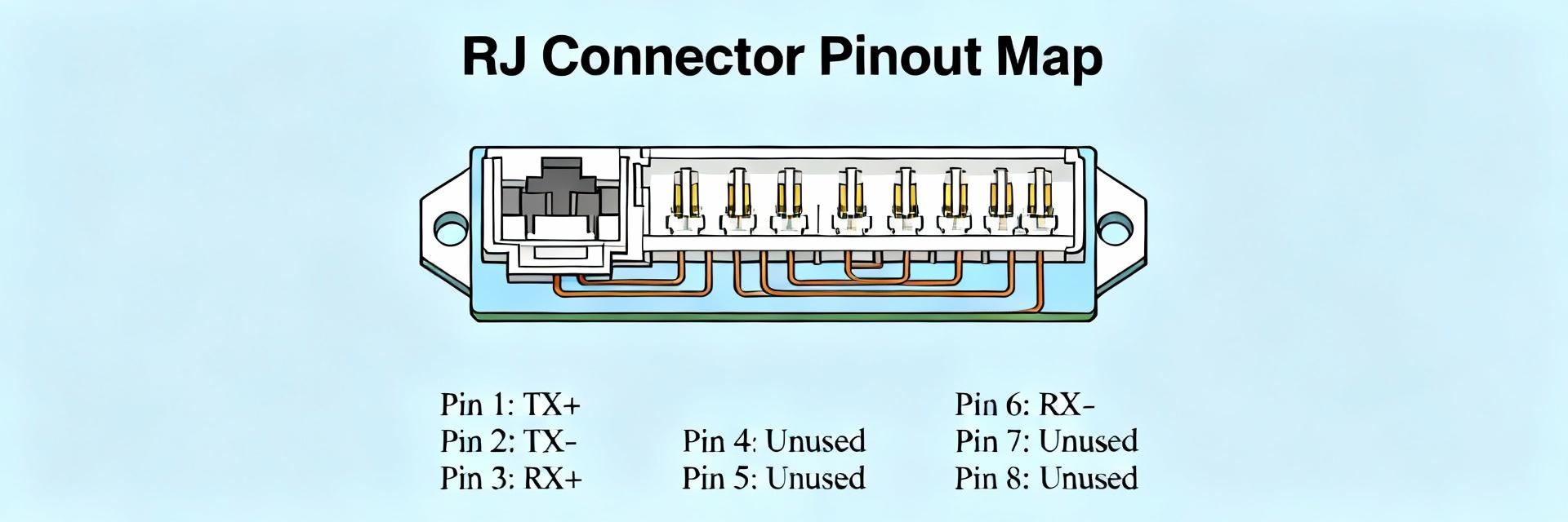
A reliable pinout map prevents routing mistakes and miswired test fixtures. The connector typically exposes differential pairs and multiple shield tabs.
| Pin Number | Function / Typical Net | Signal Direction |
|---|---|---|
| 1 | TX+ (Transmit Data Plus) | Output |
| 2 | TX- (Transmit Data Minus) | Output |
| 3 | RX+ (Receive Data Plus) | Input |
| 4 | RX- (Receive Data Minus) | Input |
| 5–6 | LEDs (Status Indicators / Optional) | Power/Logic |
| Shield tabs | Chassis / Board Ground | Grounding |
! Recommended Tests
- • Electrical Bench Tests: Perform 4-wire contact resistance measurements and loopback tests.
- • Mechanical Validation: Run mating cycle and vibration tests while monitoring resistance drift.
✓ PCB Design Checklist
- • Footprint Accuracy: Follow datasheet reflow notes for fillet size and land pattern.
- • EMI Routing: Maintain controlled-impedance differential routing and stitch ground vias.
Troubleshooting & Common Failure Modes (Action)
Symptom-driven diagnostics
For intermittent links, inspect solder fillets and measure contact resistance; for high bit error rates, capture eye/TDR traces to locate reflections.
Repair & replacement criteria
Excessive contact resistance drift, visible deformation, or failed mating-cycle metrics indicate immediate replacement needs.